
 Always Ready, Dual Flash Stands
 Aux Sync Jack Mods - Flash Units
 Hot Shoes and
Other Couplers
Hot Shoes and
Other Couplers Lens Mounted & Other Triggers
 Misc Custom
Connections / Projects
Misc Custom
Connections / Projects Off Camera Cord Mods
 Plugs, Jacks, Hardware, Repairs
 Pre-Trigger &
Motor Drive Cables
Pre-Trigger &
Motor Drive Cables Sync Cords, Other Interconnects


 CP1033c:


Note: Please remember that each of the images seen here have been made with the specific options wanted by the photog. Use these images only as a guide. Your mod will be made just as you wish, nothing more. If you have questions, please ask!
--------------------------------------------------------------------------------
(***) Topcon TRC-50EX Retinal Camera Trigger Cable
CP1116 10-24-13 Retinal Camera Trigger Cable

This Retinal Camera Trigger Cable will connect to the DB9 connector on the Topcon TRC-50EX Fundus Retinal Camera, and allow an attached digital SLR camera to be triggered, and then send the flash sync signal when the camera shutter is open so that a properly exposed image can be digitally stored. This particular cable was made for a Nikon D5200** that uses the MC-DC2 remote trigger plug, but any connector can be used depending on the particular DSLR you are using for this application. This cable is $295 (specific camera connector is an additional $55). For cable lengths longer than 30 inches, add $25.
**Note: This same cable has just been tested with the Topcon TRC-NW6s Digital Fundus Camera, along with the Nikon D70s digital camera, and is available for the same price as above.
(***) Flash Sequencer: 6 Flash Units in Sequence
CP1115 6-11-12
 The Flash Sequencer has been a project in the works in various forms for some time. This version was made to sequence 6 and only 6 flash units to fire within 1/60 th of a second, as requested by the photog for a specific moving propeller photo shoot. When triggered, either from the panel push button, or through the mini jack input from a radio receiver, hand trigger, foot switch, or directly from a sync cord attached to the camera, all 6 outputs will be active in sequence, one at a time, with the interval determined by the Timing Adjustment on the side of the unit. More advanced versions can have additional controls to "step through" each output (manually, automatically, or from a remote trigger input), fire all the ouputs at once, control how many of the total number of outputs will be active, and vary the contact time of each output (which is needed if it is desired to connect cameras to the outputs). Additonal timing ranges can also be added using DIP switches, or a rotary selector switch, all to suit the specific needs of the designed use. The total number of outputs, and the specific type of controls is only limited by the actual design specs, and naturally your budget. The version as shown, for sequencing 6 and only 6 flash units from a single trigger event, with just a single timing range is $625.
A__(***) Countdown (Pre)-Trigger Control Box
CP1001

Here is another custom designed and assembled item: the Countdown (Pre)-Trigger Control Box. This Countdown Control Box can accept any momentary switch closure (Foot Switch, Pocket Wizard, Manual Tripper, etc) as an input through the mini jacks on the box left side. The countdown is displayed by LEDs on the top surface of the box, and externally through the RJ45 jacks and LED Harness, (seen in the next image). The Control Box itself is wired as a 5 stage
 countdown timer with a 5 LED display (4, 3, 2, 1, SHOOT) on the box itself. On the SHOOT command (time zero), the output mini jacks are activated to fire the camera through the attached cable. The RED switches will alter the number of stages so the actual countdown can be any number 1 through 4, or just an immediate SHOOT signal (red LED). The LED Harness currently shows just 3 LEDs, based on the current desires of the customer, but the breakout
  box and harness can easily be altered as needed, as can the time interval between the different stages. The mini jacks on the box right side are outputs to accept a Standard Pre-Trigger Cable or one of the Special Pre-Trigger Cables as used for the USB-MutilMax Pocket Wizards.
This image (at left) shows how an early sketch and e-mail notes gets turned into a finished custom item. The Foot Switch with Heavy Duty Cable (just below) is just one way to activate this Countdown Control Box, along with a radio transmitter / receiver set, or
 Manual Tripper, as mentioned above. Other Foot Switches can be found in the Lens Mounted Trigger Section, here. Power is best supplied to the unit using a plug-in transformer, 9-12 volts DC although a battery pack will
  also work. The coaxial power in jack on the lower left face is polarity protected to prevent burnout of the sensitive integrated circuits.
In this image, all the jacks, switches, and LEDs are labelled to show the specific use.
The Countdown LEDs are currently lit one at a time, in order. For another similar project, the LEDs are lit as a true countdown, in that all 4 LEDs are first lit, then just 3 LEDs, then 2 LEDs, then 1 LED, and then none are lit for the trigger. This method has a more intuitive look to the observer as to when the time 0 trigger event will occur.
 Here is a very similar version of this Countdown Trigger Timer Control Box, although the red stage selector switches are not included. Each stage is fully adjustable, as is the delay bewteen pressing the trigger (footswitch), and the lighting of the first LED.
  If you are not using a true physical "booth", in which you can mount the SuperBrite LEDs, you can have the LED Display Unit attached to the tripod holding the camera (use your own SuperClamp and spigot into the threaded insert) so the LEDs are in easy view of the subjects. The actual display can either be in Sequence (one LED at a time), or as a Countdown (3 lit, then 2 lit, then 1 lit, then none lit). Naturally, the Control Box being used must have the countdown ability, and not just a single delay.
 Why Do you Need This Countdown Control Box?
This Countdown (Pre)-Trigger Control Box is especially useful to automate the sequence of portrait photography, candids or posed, self taken or operator assisted, as the countdown LEDs will repeat the visual sequence exactly the same each and every time. Triggering the automated sequence can be done by an operator, or by the subjects themsleves. By connecting a Manual Tripper to the output side, the operator can shoot an immediate image, bypassing the visual cues of the countdown LEDs and possibly catching a truly candid moment. A standard wired timer control like the Canon TC-80N3, or the Nikon MC-36 can be used as an interval trigger instead of this custom setup, but it will obviously not be as full featured with all the inputs and outputs and indicator LEDs.
What Does This Cost?
(Ask for current pricing.)
(***) Timer Pre-Trigger Control Box - 4 images
CP1001A 2-17-12
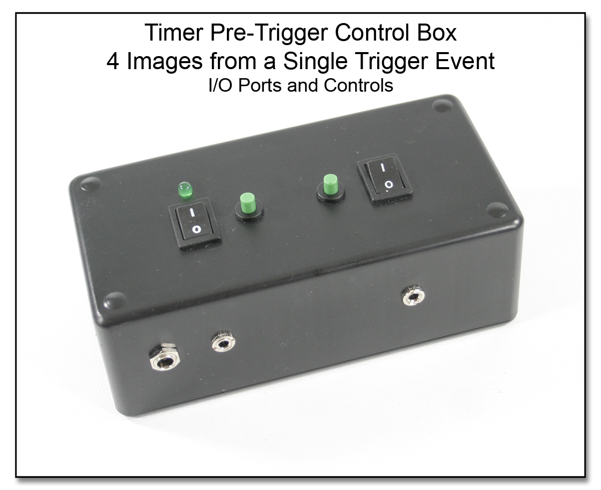 For another requested Photo Booth operation, this Timer Pre-Trigger Control Box will take up to 4 images with an adjustable delay between each one following a single press of the footswitch (or other input trigger, wireless or wired). Each of the delay sections are preset to about 2 seconds, but can be varied on setup as needed. There is no visual LED countdown with this setup (as seen in item CP1001, above) but it could be included if ordered with that feature. An AC adapter supplies the needed power, although an external battery pack can be used if AC power is not easily available.
A Footswitch with Crushproof Cable, such as item LT1021
For another requested Photo Booth operation, this Timer Pre-Trigger Control Box will take up to 4 images with an adjustable delay between each one following a single press of the footswitch (or other input trigger, wireless or wired). Each of the delay sections are preset to about 2 seconds, but can be varied on setup as needed. There is no visual LED countdown with this setup (as seen in item CP1001, above) but it could be included if ordered with that feature. An AC adapter supplies the needed power, although an external battery pack can be used if AC power is not easily available.
A Footswitch with Crushproof Cable, such as item LT1021
LT1021:
Foot Switch with
Crushproof Cable ($195), Manual Tripper Comparison (LT1028

LT1028 (SC1042):
Manual Tripper
Small vs Large), or wireless radio input will trigger the device, and then the only output needed is to connect a 3 wire Pre-Trigger Cable PT1005

PT1005:
Pre-Trigger Cables
3 wire MultiMax USB / FlexTT5 ($105) to your camera. The 3 wire cable makes use of the Pre-Trigger Override Switch on the right side of the Timer Pre-Trigger Control Box. If you already have a Pre-Trigger Cable, you will most likely want a second output jack added ($45) that will work with 2 wire Pre-Trigger Cables. The Pre-Trigger Timer Control Box (as shown), set up to take 4 delayed images from a single input trigger is $625.
A set of Stage Selector Switches ($60) can be added as an option to select just 1, 2, 3, or all 4 images to be taken following the trigger input. Adding the countdown timers, and SuperBrite LEDs for the visual countdown will add $420.
A3 (***) Airport Int'l Roller Converted to Backpack
CP1102
 Some of the ThinkTank Rollers already have backpack straps built in, but my Ver 1 Airport Int'l did not, so here is a mod for connecting the backpack straps, and still looking as professional as ever. The image with the straps in place is below. Custom made and sized
  angle brackets were made to support the D-Rings that are tucked under the upper handle (image left); the padded straps can connect or disconnect in just seconds, and can be folded and easily stored in the outer pocket if needed. The straps are fully adjustable, have extra D-Rings, and attachment points
  as you might expect from a good quality backpack. The extra padding usually seen around the hip area of a backpack is naturally not included to conserve the bulk, but the setup was easily carried through the parking lot and airport along with other luggage on a recent trip to Italy.
Adding the 2 custom angle brackets, and 4 D-Rings is $125, and the padded clip-on backpack strap assembly is $75 for a total mod fee of $200 + S/H... As should be pretty obvious, a mod like this is probably not really cost effective for most photogs...unless you can do this yourself. It is probably easier to just buy one of the rolling bags that already have the straps included, and then use the bag without the straps for the times when only a roller case is needed!
A4(***) Low Profile LANC Port Extension Cable
CP1103
 This Port Extension Cable has been made to allow the LANC Shepherd or the LANC Shepherd Pro remote control plug to take on an extra low profile when it is plugged into the video camera. This is needed on many video cameras because the LANC jack is usually located just under the video monitor, and a normal sized plug will then prevent closing this video monitor. The normal plug of this size will extend out 13.61 mm (0.53 inches), while this Low Profile Plug extends out 7.00 mm (0.275 inches), and should allow the video monitor to just about fully close. The attached very flexible flat cable is made of parallel wires, and is only 1.40 mm (0.055 inches) thick. This Low Profile LANC Port Extension Cable, item CP1103, is $150.
A5(***) Flood Light: Handheld, Variable Pwr, Zoom
CP1105 (7-14-10)
 Here we have combined a Dedolight (DLH4) Universal Quartz Halogen lamp head with a variable output rechargeable 18 volt battery pack to achieve an easy to hold, easy to use light source with a zoom control of the beam width, and a variable light output in color temperature. (Click on any image to enlarge in a new window.) The Dedolight unit is ultra-compact in size with a light output equal to units of a much larger size. The 2 aspheric lenses make for a very clean light beam which can vary in width by adjusting the zoom control lever on the light unit. Varying the voltage to the lamp through the ergonomic trigger and
 handle of the one time DeWalt 18 volt cordless drill, the light source is dimmable through a wide range. Drop ship each of these items to me, and I can modify each one to become a combined unit for the
 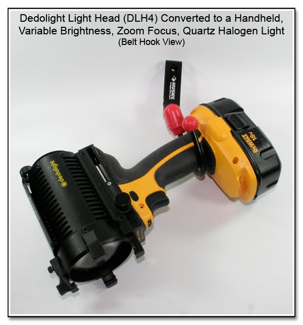 introductory price of $175, (light and drill not included). There are many models of these cordless drills which can be used for this combination, and there might be slight differences in the final assembly costs depending on the exact model, and the nature of the housing as the mod progresses. Testing has just shown that this particular NiCad battery (at full power), was drained in 15 minutes. A double capacity battery that has a thicker base (DeWalt XRP) is also made for this model, and should provide twice the running time of the slim line battery shown. Normally you would use this light for just seconds at a time, so the total time used will likely be greater than when used in a constant on mode. The newer models of cordless drill often use Li-Ion batteries, and although more costly to start, they are lighter in weight, and should have a longer run time with less of a memory factor. The same model shown in these images is now available in the Li-Ion version, which is 14 onces (390 grams) lighter. Using a belt clip ($10) similar to that shown in this last image, the light unit can hang on your side and be ready for use in just a moment.
A0(***) Canon RC-1 Mod for Remote 7D Movie Mode
CP1006
 The Canon RC-1 Remote Control (when set to position #2) can be used to remotely start and stop the movie mode of the Canon 7D, although since it is an IR based remote, it is limited to a line of sight transmission distance of about 15 feet. With the RC-1 set in position #1 (the small dot), a single still image will be taken with the 7D or any other Canon camera that has the IR remote receiver built into the self timer. Should the 7D already be recording a movie when the RC-1 signals a single image, the movie recording will pause, and a single image will be recorded, and then the movie will resume.
The RC-1 External Connection Mod will allow a Pocket Wizard radio set (or a hardwired extension cable) to trigger this Canon RC-1 in either the postion #1 (single still image) or position #2 (movie mode for 7D, 2 second delay for other cameras), and thus increase the remote control distance from a meager 15 feet to whatever distance can be achieved by the Pocket Wizard radios. This mod of the Canon RC-1 is $120, and the RC-1 must be supplied separately for $35.
I now have a supply of this RC-1 item available for this mod, although the clip-on cover that can be attached to the camera strap does not come with this item.
As an interesting scenario, use a setup of 2 of these mods, and 2 PW's, and you can remotely start a movie with one modded RC-1 (set in position #2), and during the recording take a still image with the other modded RC-1 which will pause the movie, before the recording resumes after the still image has finished being written to the memory card. I have a new item, the IR Remote with External Connections (just below) that will output either of the IR signals (the "Shutter", or the "2 sec delay"), and has 2 separate mini plugs, instead of the one shown above.
(***) Skyport Radio Notes for IR Remote Mods:
The switch closure pulse of the Skyport receiver is so "short and noisy" that it can not be connected directly to the modded Canon RC-1, or the 2 Button IR Remote (below), as the PW's can. An interface is needed between the two devices to lengthen the signal, and provide a noiseless switch closure. This interface can be made as a single channel unit for $150, or a dual channel for $200.
A00(***) Canon IR Remote - External Connections
CP1101
 This special mod turns an ordinary 2 button IR remote (Canon version) into an IR Remote with External Connections specifically, but not limited to, the Canon movie mode of the 7D. Like the original RC-1 Mod (just above), this remote will operate either the movie mode, or the still image mode, alone or together. In addition, one cable end has an extra IR LED that can be taped over the camera IR sensor, and will then activate the remote functions. This makes for an easier mounting of the device, so only the IR LED on the external cable needs to be in front of the camera sensor. (The Skyport Radio Notes mentioned above also apply here in using the 2 Button IR Remote.)
This IR Remote with External Connections, to include the basic remote, 2 mini plug inputs for the "Shutter" and the "2 sec" delayed shutter (movie mode of Canon 7D), as well as the External IR Emitter is available, and will cost $235.
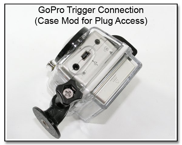
<!- GoPro Trigger Remote Connect CP1114 --> (***) GoPro Trigger Remote Connect
CP1114 5-10-2012


<! Nikon IR Remote - External Connections CP1101A--> (***) Nikon IR Remote - External Connections
CP1101A 11-28-2011
 The Nikon IR Remote Control Transmitter (ML-L3), (image left), can be connected and fired from any RF type of radio set as a way of getting extended range, longer than the usual 15 or so feet of the normal IR unit. Adding the mini plug on a short cable into the Nikon ML-L3 Remote Control Transmitter is $130, plus the cost of the ML-L3 unit. Just as with the Canon unit (above), an extended IR Emitter can also be added into this ML-L3 unit so that just the IR Emitter itself can be taped in view of the IR Sensor of the camera. It would be $230 to have both cables tied into this ML-L3 controller unit.
A1(***) Cell Phone Camera Trigger - (Receiver Unit)
Fire Your Camera from Anywhere!
CP1007
 The Cell phone Camera Trigger is shown here as a hardwired, single camera version, and is ready to accept a single key press to trigger a camera from a "receiving" cell phone. The sub-mini plug fits into a standard cell phone headset jack, and the N3 plug connects to a Canon camera (other INPUTS and OUTPUTS are also available). Set the "receiving" cell phone to auto answer (many phones automatically go into auto-answer mode when you plug a cable into the headset jack), and connect the Cell Phone Camera Trigger between the camera and the cell phone, and then call this "receiving" cell phone from anywhere. Press number "7" on the "transmitting" phone while the connection is open, and the camera will fire an image with each key press (see below for the Burst Mode Firing option). Some older cell phones will send a tone for the length of the key press, and then this option may not be needed to get a burst mode camera firing.
Field test review:
"The Cell phone trigger works great. We had no miss-fires with over 70 photographs using the Cell phone trigger last night."
(***) Controls and Costs:
One switch and indicator LED is for the power supply (9 volt battery), and the other switch is the Pre-Trigger ON/OFF. When the circuit "hears" the correct DTMF tone over the open phone line, the relay will close, most often for just a short pulse, and the green LED will light. As mentioned above, some older cell phones will send a tone for as long as the key is pressed, and then this option would not be needed. The delay from when you press a key on the "transmitting" phone to the actual camera firing is very slight, but will vary somewhat based on the cell phone transmission connection. The delay will be naturally longer than with any radio set (Pocket Wizard), but the triggering range is only limited by having a valid cell signal at each phone. As shown, this setup is $275 (for a limited time). Other camera connectors are available for the same cost, but it is an additional $25 to use this with the iPhone or Blackberry devices, as a special 4 conductor mini plug is needed for the "receiving" phone. To keep this a simple and safe design, the input and output cables are hardwired into place. An available option ($25) would be to have an additional mini plug input so that this box can be used as a standard Pre-Trigger Cable for radio sets (Pocket Wizard) when the power is OFF.
(***) Camera Burst Mode Option:
When the cell connection is made, the "receiving" cell will usually pass along a short tone to trigger the relay, and not a continuous tone as needed for a camera burst mode. (As mentioned above, some older cell phones will send a tone for as long as the key is pressed, and then this option would not be needed.) To make a longer duration relay closure, a Variable Timer Module can be added internally to the Cell Phone Camera Trigger, and would be activated by pressing the number "8" on the "transmitting" cell phone. Pressing number "7" will still make the short duration relay closure for the single image exposure. The relay closure time range is adjustable through a small port in the box, and this feature will add $125 to the total cost of the unit if it is done when ordered, or $150 if the option is added as a retrofit.
(***) Important Safety Note:
This custom built item has no user servicible parts, other than adding a 9 volt battery through the battery door on the reverse side of the unit. This device is to be used only to remotely trigger a camera through the attached camera cords, and has no other purpose, intended or otherwise.
A2(***) Cell Phone Camera Trigger - (Sender Unit)
Connect to Lens Mtd Trigger or Manual Tripper
(Image and Pricing Coming Soon)
When using the Cell Phone Camera Trigger, after a cell connection is established between the two phones, you need to press a key on the "sending" cell phone so the "receiving" cell phone can hear the correct tone, and fire the camera. This External Trigger Sending Unit can plug into the headset jack of the "sending" cell phone and send a tone, in a similar fashion to a land line auto-dialer. In this manner, you can use an external trigger like the Lens Mounted Trigger, the Stick-On Trigger, the Manual Tripper, or even a Foot Switch so you don't have to hand hold the "sending" cell phone. If you have the Cell Phone Camera Trigger with the Burst Mode Option (longer duration adjustable secondary tone), then you will likely want this setup with the capability to send the 2 different tones as well. There are times when using this External Trigger Sending Unit will activate the phones voice menu or possibly another menu or unwanted function. If that is the case, you will have to use a different cell phone as the "sending" unit, or select a different set of tones to be used. (When selecting different tones, the "receiver" unit must also be tested to be certain the tones are being transmitted properly, and still fire the camera.) Please keep in mind, that due to the numerous cell phones continually being introduced to the market, many with different digital signal protocols, not every combination can be tested in advance. I am more than happy to test a set of your phones to see just what options you might require. Another connection option from the "sender" unit to the "sending" cell phone is using the Acoustic Coupler Module that can also be built into the "sender" unit.
B(***) AF Assist Unit - External (Self-Powered)
(***)Why Do You Want This?
CP1008
 The External AF Unit is another specialized, customized unit that will "relay" the AF signal from a flash unit where the AF Assist light is being blocked by a ring flash attachment of other device (see below), and project it out from the front window of this unit with the same grid lines as the original. Click on any of the images below for the enlarged details, but this version is housed in a box only 3.5 x 2.5 x 1 (inches), and is powered either by an internal 9 volt battery, or by an external power supply through the included Aux Power input jack. The back of the unit has an Internal Sensor, or the External Sensor can be plugged into the mini jack just above the Aux Power input jack. The unit has both a manual Test button, as well as a Manual Tripper that can plug in just above the External Sensor jack.
On the other side face (image above which you can call the left or the right face, depending on which way you are holding the unit) are the other controls, obviously the ON-OFF switch and indicator LED, the Test button (which is disabled when the external manual tripper is plugged in), the Sensor adjustment, and the sensor indicator LED, the DIP Switch controls, and the AF Assist Indicator LEDs. The 3 AF Assist Indicator LEDs blink when the corresponding front panel AF Assist LEDs blink, to give a visual indication of firing. DIP Switches 1, 2, and 3 control each of the 3 AF Assist LEDs, so that any conbination of the 3 LEDs can be lit up. DIP Switch # 4 turns off the AF Assist Indicator LEDs as a way of blanking the side display (but doesn't blank the main AF Assist LEDs on the front panel). DIP Switch # 5 is to blank the Sensor Adjustment LED, and DIP Switch # 6 is to blank the Power Indicator LED. Blanking the side display LEDs will save a little bit of battery power, and prevent all the blinking LEDs from possibly being a distraction to others when shooting in a dark room.
The Bottom Line:
Custom items of this complexity sometimes require a rather long lead time for analysis, design, and prototyping, and will often start in the $400 to $500 price range. Please remember that these are not mass produced items, but are hand designed and built to achieve a specific purpose based on your needs and desires.
Using a larger enclosure, eliminating the DIP switches, Test button, and having only a single External Sensor would make for a simpler version that is both easier to construct, and would cost less overall.
(***)External AF Assist Unit - Why Do You Want This?
If the AF Assist light from your flash unit is being blocked by a ring flash attachment or other device (see below), this External AF Assist Unit can be placed in front of the the ring attachment, and the


 external sensor is then taped to the front of the flash unit AF Assist light. When the AF Assist light from the flash unit fires, the sensor triggers the External AF Assist Unit to also fire, and emit the light from either the 1, 2, or 3 AF Assist lights.
C(***) AF Assist Unit -External (Remote Powered)
CP1013
 This AF Assist Unit is a passive unit, in that it is completely powered by the flash it is connected to. A special jack is installed into the master flash, and the external AF Assist unit is connected via the connecting cable. The AF Assist Unit can then be attached to the front of a ring flash adapter to provide an uninterrupted AF Assist beam. This specific 580EX II flash unit also has a mini-DIN connector coming from the left side of the flash (right side of the image). This mini-DIN connector is tied into the foot assembly contacts to connect into a flash end having a mating mini-DIN connector to provide a "zero height" Off Camera Cord.
(***) AF Assist Unit New (Auto / Manual / Timed)
CPxxxx (9-23-15)
Image and details soon!
D(***) Custom Modded 580EX II - Zero Height OCC
CP1014
 This Custom Modded 580EX II flash unit has several very interesting mods: first is the Zero Height Off Camera Cord built into the foot assembly of the flash unit has been done so that the main on camera flash will not be rasied up by ANY distance above the camera hot shoe. This is especially critical when using any type of ring flash adapter, which is sized to keep the camera lens exactly in the center of the circular ring flash adapter. Having the Zero Height Off Camera Cord built in, a second flash unit can provide fill or spot lighting at the end of either a short or long mini-DIN extension. Also shown in the image is the Flash Selector Switch, which will allow either one or both flash units to operate in eTTL mode, without having to physically disconnect one flash or the other. If you just power one flash to OFF, the other flash will revert to TTL mode instead of eTTL mode, and your exposure will be way overexposed. The External AF Assist Connection Jack, which is located on the right side of the flash (not seen in this image), and will transfer the AF Assist lamps to an external device that can be attached to the front of a ring flash adapter, as seen in the AF Assist Unit - External (Remote Powered) post just above.
E(***) Flash Selector Switch (3 Position)
CP1015
 Here is a closup of the actual Flash Selector Switch that has been installed into this 580EX II flash unit. Having 2 EX flash units connected to work in eTTL mode via any type of custom Dual Linked Off Camera Cord, this Selector switch will allow either flash or both flashes to be fired, while still in eTTL mode. Normally you would have to physically remove one flash from the circuit, as just powering one flash to OFF will NOT allow the remaining flash to operate properly. What does occur however is that the flash that is still powered ON will revert to TTL mode, and then give you an overexposure. This 3 position selector switch can be placed into any Canon EX flash unit that also has the Zero Height Off Camera Cord, which is the camera portion of the OCC built into the foot assembly of the flash itself! The cost to add this 3 position Selector Switch is $150
F(***) 3 Stage Custom Timer
CP1016
 This 3 Stage Custom Timer again shows just some things that are possible, and only limited by your imagination. This adjustable timer was specifically made to fire two cameras with the second camera delayed from the first by a set amount. For this specific project, 2 cameras are being used, each in burst mode. Each camera will take images in a 1 second burst, with the second camera being started just before the first camera has finished shooting. The DELAY period, as well as the time ON of each camera is adjustable as needed. The timer unit can be triggered by pressing the red momentary push button, or by using an external trigger, such as the Manual Tripper shown, or even via a radio set such as the Pocket Wizard. The three LEDs along the top of the unit indicate the ON time of the first camera, the DELAY before the second camera starts, and the ON time of the second camera. For this project, the time adjustments are made using a small screwdriver from within the battery compartment as a way to keep the clutter on the operating panel to a minimum. The adjustment POTS could have been made to be visible alongside the corresponding LED, but that was specifically not requested. This same setup can be extended to just about any time period, short or long, and with any number of camera outputs, and delay sequences, all depending on the specifications required. A truly digital version, where the timer starting values can be set on a numeric display for each timer section is also in the works. Being strictly a custom designed unit, this type of trigger as shown would start at around $450, depending on the features desired.
Update: The customer photog was able to adjust the overlap between the 2 cameras quite easily to indeed get the minimal frame overlap as desired. A slight overlap is needed to aid in syncing the two camera burst sequences.
G(***) 3 Stage Custom Timer - Advanced
CP1017
 This Adjustable 3 Stage Timer is based on the same design as the version above, with some very useful additions, and like most everything else here, was designed with input from the purchaser. The timer adjustments can be seen recessed through the small holes just below the corresponding indicator LEDs (click on the image to enlarge in a separate window), and the upper black colored switches are for manual control of each camera output jack, or the combined cable RJ45 jack. The small black rocker switch
 controls the pre-trigger action when in manual mode, and is automatically engaged when in the auto mode. In addition, in auto mode, the manual pushbuttons are disengaged to avoid inadvertant firing in the manual mode. The underside of the Timer Box has an easy to access battery compartment, and a threaded insert for mounting the unit as an alternative to the flexible lanyard. The RJ45 combined output jack will allow a single ethernet cable of any length to connect to a Splitter Box (below), which then has outputs to the 2 cameras. This way the Timer Box
  can be mounted either at the camera location, or at a distance away from the cameras, and still operated in either the auto or manual modes. The setup here also includes a Manual Trigger Box, which has none of the timer auto electronics, and is meant to be used either as an additional Splitter Box, or in case the Timer Box has to go in for upgrades and servicing, or just as a smart backup (like in case the Timer Box gets stepped on and crushed by your helpful assistant). The mini jack on the side of the
  unit allows connection from a Manual Tripper, Foot Switch, or the connection to a radio receiver set for truly remote operaions.
If you are interested in this item, or something similar to fit a particular need or desire you have, send an e-mail with some info and together we can figure it out!
New Projects in the Works:
1) Flash Verification Annunciator - When you have multiple flash units being wirelessly triggered, and some are out of sight, some are in softboxes, etc, it is often times hard to make sure they all fired. This unit has a small wired sensor placed in front of the flash unit, and will sound a tone, or blink a sereis of LEDs to indicate that the unit has fired. All aspects of the blink and tone are adjustable to each specific annunciator unit will look and sound unique from the next unit. The annunciator unit also has output jacks for the internal relay, and an external speaker.
2) Flash Cycler for rapid sequencing of multiple flash units, either in manual firing mode, or triggered by a burst mode from the camera (coming soon).
H(***) FreeXwire FW9T Input / Output Mod
CP1021
 The FreeXwire FW9T Transmitter can be set to locally fire an attached flash unit, just like the FreeXwire FW8R Receiver. Both the FW9T and the FW8R will fire a flash that is attached through the PC jack, but only the FW8R Receiver will fire the flash through the mini plug located on the right side...unless you have the FW9T Input/Output Mod done. Now the mini jack on the FW9T Transmitter, which is factory marked as "Sync In", will now behave as "Sync In /Sync Out", and a flash can be fired by connecting to either the PC jack , or the mini jack of the FW9T Transmitter unit. This fee for this mod is $55, and like most of my mods, will usually take just a day, will naturally void your warranty, and will obviously need to be sent to me for the mod to be done. (Other than all that, it works great, and lets you not have to rely on the PC jack for a connection.)
I(***) RadioPopper PX Mounting Bracket Mod:
Single Fiber Optic Bundle - SpeedRing Mount
CP1022
The new RadioPopper Mounting Bracket for the PX Receiver works really great for securing the RP to the flash head in the correct placement in front of the IR sensor. The biggest problem with this

 placement is that it takes up about an inch or so in front of the flash, and this will sometimes interfere with the mounting of the flash in many softboxes. Take a look through these images (click on any to open in a new window), and you will see an alternative
 mounting using a Custom Guide Block that is bonded to the RP Mounting Bracket, and a "throwback" method to directing the IR beam directly to the IR receiver window. The flash can now be moved closer into the softbox ring without having the RP get in the
  way. This same Custom Guide Block can be used in splitting the IR signal into 4 fiber optic bundles, as seen in the images just below. The FourSquare Bracket, which combined with the fitted softbox, provides an easy way to secure all four flash units in a compact mounting, and have an easy to use, and rather large softbox.
Costs and Fine Print:
To fabricate and bond the Custom Guide Block to the RadioPopper Mounting Bracket is $95. Fitting a single fiber optic bundle into the Custom Guide Block is $35 plus the cost of the bundle itself. The fiber optic bundle are $25 each for up to a 12 inch length. Hardly anyone is using the clear reflector tips anymore, as the Holding Band (CP1030A

CP1030A:
Fiber Optic
Holding Band on
580EX Flash Unit $13) seems to keep the tip in the proper place just as well.
I1(***) RadioPopper PX Mounting Bracket Mod:
Quad Fiber Optic Bundle - FourSquare Mount
CP1027
Jump to: Cost Summary (below)
 When you wish to use a single RadioPopper PX Receiver to control 4 flash units as in this FourSquare Mount, the the IR LED beam must be split and distributed to the IR sensor on each flash unit. The same Custom Guide Block as in the single version (above) is bonded and screwed to the RadioPopper Mounting Bracket, and this is $95 which now includes the threaded and non-threaded holes but not
  the mounting studs as in the thicker version below (see image left). Blending the 4 fiber optic bundles into a single end to fit into the Custom Guide Block alignment hole is $55. Three longer length fiber optic bundles are needed to reach to the other flash units without having any sharp bends, and these longer lengths are $25 each. One standard length (7 inches) fiber optic bundle is also needed, and this item is $5 when orderd with the clear reflector tip directly from the RadioPopper site. The RadioPopper Mounting Bracket is also an item that should be ordered
 directly from the RP site. This concept of using the fiber optic bundle to split the beam using a blended bundle can also be used for 2, 3, or almost any number of flash units. Use gaffers tape or the Fiber Optic Holding Band (below) to securely attach the end of the Fiber Optic Bundle to the flash sensor window.
(***) FourSquare Links:
View Dave Black's Surfing Shoot using this Quad Fiber Optic Setup.
View Dave Black's Motocross Shoot using this Quad Fiber Optic Setup.
View Dave Black's Hockey Shoot using the Quad Fiber Optic Setup.
Get more info on the FourSquare itself from LightwareDirect.
Go to Dave Black Photography, and check the Workshop at the Ranch.
"FourSquare and EightSquare Assembly" by Dave Black
Mounting Note: The mounting of the PX Receiver using the RP Mounting Bracket and the Custom Guide Block is made to be mounted in several ways, up to the needs of the photog. It can be mounted to the side of a flash unit with the Velcro, and that is why the Custom Guide Block only covers half of the RP (modified) Mounting Bracket, and the Velcro covers the other half, in order to give an offset "lip" where the Velcro holds tight. The included metal thumbscrew can be inserted into any of the threaded holes to grip tight against either a section of unthreaded 1/4 inch rod, or against a section of 1/4 inch threaded rod, again, only limited by your imagination. Extra mounting hardware is available to secure the Custom Guide Block to one of the threaded holes in the FourSquare Bracket for just an additional $10.
The Custom Guide Block that is attached to the PX Mounting Bracket has several mounting holes, depending on the exact method of mounting you desire, and one of the holes is a through hole, and is sized for the Blended Fiber Optic Bundle, which is then GENTLY locked in place using the nylon thumbscrew. This hole is lined up right against the IR Emitter of the actual PX Receiver, and that's how the IR light gets into the Blended Fiber Optic Bundle. Each of the 4 ends of the Fiber Optic Bundles are then slid through a hole in the Holding Bands, and positioned flat against the IR Sensor of the flash. While it would be more light efficient if the bundle were at 90 degrees to the surface, it still works fine at 0 degrees (flat), and takes up less room than if it were to be sticking straight out.
(***) Fiber Optic Bundle Holding Band
CP1030A
 The Fiber Optic Bundle Holding Band keeps the end of the Fiber Optic Bundle (or one of the IR Emitters) in the correct position against the IR Sensor Window for either the Canon or Nikon flash units by using a high strength Velcro band and a compressible foam pad bonded to the inside surface of the band. The Velcro band is rated at 10,0000 cycles (opening-closing)
  and at a temperature range of -70 F to +200 F. Gaffers tape is not needed, but can be used to aid in the initial positioning of the fiber optic on the IR sensor, at least until you are comfortable getting the Holding Band in place and tightened into place. This Fiber Optic Holding Band is being introduced at just $13 each, and is shown below as a line item in the Cost Summary as a set of 4 for $48 and which now includes the Safety Ring, and the 3 foot Nylon Flat Rope for a safety tether.
A new way to secure the fiber bundle is using the fiber Optic Bundle Holding Clamp (CP1113

CP1113:
Fiber Optic Bundle
Holding Clamp (580EX)) that makes it quick and easy to correctly position the fiber bundle in place over the IR sensor. Unfortunately, being a custom molded item, the current version with the Extended Leg is $55 each.
Add a Safety Ring (PJ1091
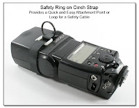
PJ1091:
Safety Ring on Cinch Strap:
Quick and Easy Attachment Point or
Loop for a Safety Cable) to the Holding Band for just $4 (now included for no extra cost), and this will provide a very easy, simple, and secure way to thread any safety cable, rope, string, or sync cord wire to use as an extra tether to keep the flash unit from falling to the ground, and possibly causing injury or other property damage. If you need 1/16 inch stranded aircraft cable Safety Cables, see items PJ1053

PJ1053:
Safety Cable
with Attached Swivel Hook and
Pre-Formed Loops or PJ1054

PJ1054:
Safety Cable
with Snap Hook. Also available is black nylon small diameter round (or flat) rope that can be easily tied for use as a safety tether for just $4 for a 3 foot section. The Safety Ring, and 3 foot Nylon Flat Rope are now included with the set of 4 Cinch Straps (PJ1091
PJ1091:
Safety Ring on Cinch Strap:
Quick and Easy Attachment Point or
Loop for a Safety Cable) for $48. Unlike the Holding Bands, the Cinch Straps do not have the pre-punched hole, and the foam section is left unattached.
 A version of the Fiber Optic Holding Band set up for the Nikon flash units with the add-on 5th battery compartment is also available, and is shown (left). The offset guide block holds the fiber optic bundle against the IR Sensor window, while the outer band applies pressure and still will bypass the protrusion casused from the extra battery compartment. This Fiber Optic Holding Band is $20 each, or a set of 4 for $72. (The image shows a Canon flash unit, but the Holding Band and offset block is made for the Nikon flash with the external 5th battery.)
(***) Cost Summary Quad Fiber Optic Setup:
All the individual fiber optic bundles are now being made at the same 12 inch length as to make for a simpler, more universal design which can be used with any flash brand. This makes it easier in routing the bundles, and allows for a more varied mounting of the PX Reciever itself. Again, this one setup uses all 4 bundle at 12 inches long for either the Canon setup or the Nikon setup.
(***) Fiber Optic Bundle Holding Clamp 12-24-11
 Here is a new method of holding the Fiber Optic Bundle in place without blocking the rear LCD screen: the Fiber Optic Bundle Holding Clamp. Currently, this item has only been made for the Canon 580EX unit, but it can be made for other flash units as well. This item is custom molded to grip the flash body, positions the Fiber Optic Bundle at a 90 degree angle to the IR sensor of the flash unit, and currently costs $45 each. The newest version has the Extended Leg to prevent the sliding movement of this original version, but is $55 each. Additional images can be seen below.
I2(***) "Quad Fiber Optic Setup" Complete Kit Price:
Complete setup of PX Bracket w/ Custom Guide Block, Blended Fiber Optic Bundle (4 x 12 in), Mounting Stud w/ Nuts: $390 + S/H. The Holding Bands are $48 additional.
To make up a "Dual FourSquare" (or as Dave Black calls it an "EightSquare"), you will need a second complete set of the above Quad Fiber Optic Setup ($390), the Extra Parts Mounting Pack ($20), and the Custom Spacer Block (CP1033e
Dual Custom Guide Block
Assembled from Two
Single Custom Guide Blocks
Assembled View & Parts View Rigid Version: $120)
*****************************************************************************
(***) PocketWizard FlexTT5 Splitter: Not Reliable
2-10-12 Splitting the TTL signal from the Canon or Nikon PocketWizard FlexTT5 is not giving the same reliable results as seen here using the Fiber Optic or Wired IR Emitter Setup along with the RadioPopper PX units. You can use a manual splitter for the FlexTT5 units, and you will get remote firing, but this will not include remote power control, or the High Speed Sync (HyperSync) modes. Experimentation and testing has been ongoing for some time...hopefully this can be worked out sometime soon.
*****************************************************************************
(***) RadioPopper PX Signal Splitter Comparison:
Quad Fiber Optic vs Wired IR Emitter Setups:
This is all a common question now, so in 'brief' (8-1-11):

There are 2 ways to do this, outlined (and linked) just below. Seen in some of Dave Black's videos with the FourSquare (links above) are the Quad Fiber Optic Setup (CP1027

CP1027: RadioPopper Bracket Mod
Quad), that use the 4 fiber optic bundles, each 12 inches long to transmit the IR light to the flash IR sensor. The other (newer) way, that is used probably more often, is the Wired IR Emitter Setup (CP1104

CP1104: RadioPopper PX
External IR Mod
& IR Splitter). (The cables now have the newer inline splice and clear acrylic reinforcing tubes.) Dave mostly uses this newer Wired IR Emitter setup on shoots, but uses both methods in his seminars, the last I heard. Only the Wired IR Setup will void the existing warranty of the PX Receiver unit because a sync jack is installed into the PX Receiver unit so the Wired IR Emitter cable can be plugged in. The Fiber Optic Bundles are more rigid than the wires for the Wired IR Emitters, so they need a larger bending radius, and have a bit of springback, so they usually need more tape and straps (Holding Bands) to secure the tips in place over the IR sensor of the flash units. A single section of gaffers tape will usually be enough to secure the tip of the Wired IR Emitter in place over the IR sensor, since the wire cable used is very flexible. Again, because of the rigidity of the fiber optic bundles, the PX Receiver needs to be rigidly attached to the FourSquare or other bracket when using the Fiber Optic Setup, but for the Wired IR Emitter Setup, the PX Receiver can be either just attached to a single flash head with Velcro, or it can be rigidly attached just as with the Fiber Optic Setup.
The Wired IR Emitter Setup is definately the easiest to use, setup, and breakdown, and is the most flexible, both in true flexibility, and expansion capabilities. Indeed the biggest issue is the double shipping for those located outside the USA, and I am not sure if RP will ever consider changing their tune. I have asked in the past to have them marked as SOLD to the customer outside of the USA, but shipped to me c/o the buyer, but they say that is still against FCC regulations. They do often ship the units to me for photogs living in the USA.
1)(***) Quad Fiber Optic Setup (CP1027
CP1027: RadioPopper Bracket Mod
Quad):
Pricing: $390 + $10 S/H (USA)
Includes: PX Bracket w/ Custom Guide Block, Blended Fiber Optic Bundle (4x12 inches), Holding Bands (4) are no longer included ($48 additional), Mounting Stud w/ nuts
Notes: No changes to the PX Receiver unit (no voiding of the warranty)
2)(***) Wired IR Emitter Setup (CP1104
CP1104: RadioPopper PX
External IR Mod
& IR Splitter):
Pricing: $390 + $10 S/H (USA)
Includes: Sync Jack Mod to the RP PX Receiver unit, 1x4 Wired IR Emitter Cable, Clear Acrylic Reinforcing Tubes (4)
Optional Extras:
a) Expansion Jack (CP1104AB

CP1104AB:
RadioPopper PX
External IR Mod (Sync Jack)
Dual 1x4 IR Emitters w/
Expansion Jack - 1x8 Setup Shown) $75,
b) IR Emitter Velcro Mtg Tabs w/ Cinch Straps (4) (CP1104AF

CP1104AF:
IR Emitter-
Velcro Mounting Pads) $64
c) Rigid Mtg Bkt, Block, and Stud for FourSquare (CP1104AE

CP1104AE:
RadioPopper PX External IR Emitter Mod
Mounted on a FourSquare Bracket with Handle
Including the Cinch Strap with
Safety Ring and Nylon Tether) $130
d) Cutout of Standard Mtg Bkt for clearance (CP1104AD

CP1104AD:
RadioPopper PX Receiver in
PX Mounting Bracket
Showing Interference Location of
IR Sync Jack) $10
(Needed to use the PX Mtg Bracket with a single flash unit)
Setup Procedure & Testing: Newbees sometimes have difficulty getting all the IR Emitters lined up properly, especially since the human eye can NOT see the light coming from the IR Emitter as it is truly in the IR range. Jump to this section for images and the procedures I use in testing your setup prior to shipping it to you:
CP1112

CP1112:
RadioPopper PX Mounting Bracket &
Base - set for 580EX II
Showing Height of Sensor Location
Side View---RadioPopper PX Sensor Location & Testing (8-18-11)
Notes: You must send (or have RadioPopper send) the PX Transmitter and PX Receiver to me for the Mod to the PX Reciever unit, naturally voiding the warranty on the Receiver unit.
As a last note, for both methods, the PX units can still be used as they were originally intended for a single flash unit, although the mounting bracket will need a slight adjustment to clear the sync jack of the Wired IR Emitter as listed in item d) above (CP1104AD
CP1104AD:
RadioPopper PX Receiver in
PX Mounting Bracket
Showing Interference Location of
IR Sync Jack).
RadioPopper will not send units being sold out of the USA to me first, so the Wired IR Emitter setup would involve a second shipping trip, while for the Fiber Optic Setup, the PX units are not needed here for any mod. For those within the USA, you can have RadioPopper drop ship the units to me directly, although it should be sent with both my name and your name on the shipping label.
QQQQQQQQQQQQQQQQQQQQQQQQQQQQQQQQQQQQQQQQQQQQQQQQQQQQQQQQQQQQQQQQQQQQQQQQQQQ
Update 12-6-10:
Early reports from one user (Kyle P.) that his setup worked just as well without the Clear End Reflector Tubes, as long as the tip of the Fiber Optic Bundle was held in place directly and tightly over the flash IR sensor window, using gaffers tape and/or the Holding Bands. As a result, the Clear Reflecting Tips are no longer included in the $353 cost of the setup. You can always get these Clear End Reflector Tubes separately from the RadioPopper store.
I2a(***) Dual Quad Custom Guide Block - Original
CP1033
See the new Rigid Version (CP1033c
CP1033c:
Dual Custom Guide Block
Assembled from Two
Single Custom Guide Blocks
Assembled View & Parts View Rigid Version) made from 2 Single Blocks
 This Dual Quad Custom Guide Block is a specialty mounting to allow 2 RadioPopper PX Receivers to each split the IR beam along 4 fiber optic bundles for controlling a total of 8 flash units. The Dual Quad Custom Guide Block has a threaded mounting hole for attaching to the FourSquare Bracket (www.lightwaredirect.com) using a section of 1/4-20 threaded rod and some regular 1/4-20 nuts. Nylon thumbscrews are adjusted to apply a small amount of tension to prevent the quad bundles from inadvertantly being displaced from the guide holes. This Dual Quad Custom Guide Block is $140, the
  Extra Parts Mounting Pack of the cap screws and threaded rod is $20 (right side of image left), and still needed from RadioPopper are the 2 PX Mounting Brackets, and the P1 Receiver Optic Tube Ends as in the summary just above. You can have these parts sent directly to me, or I can order them for you. The Mounting Stud w/ Nuts will allow 2 of the Single Custom Guide Blocks to be joined into a
  Dual Custom Guide Block in a simple matter, as seen in the image just below. This Mounting Stud w/ Nuts is $10 and will also allow a single Mounting Block to be attached to the FourSquare. While this is a very inexpensive alternative to the one piece Dual Quad Custom Guide Block image left, care has to be taken to properly tighten and position the threaded rods and nuts so the separate parts don't wobble all around. A much better alternative is the Rigid Version of the Dual Custom Guide Block, seen just below using the center Spacer Block.
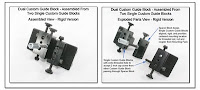
(***) Dual Quad Custom Guide Block - Rigid Version
CP1033c
 This is a Rigid Version of the Dual Custom Guide Block and is also made from 2 Single Custom Guide Blocks, but unlike the above version that is tied together with the single threaded rod, this version is held together by 2 cap screws going from one Guide Block to a set of extra threaded holes in the other Guide Block, passing through the center Spacer Block, It is this Spacer Block that keeps the Single Guide Blocks aligned, rigid, and provides a centered mounting location for the threaded rod, nut, and coupler that comes in the Mounting Pack of hardware parts. To get a better view of how this is put together, the Exploded Parts View shows the Spacer Block along
  with the 2 Single Custom Guide Blocks. Since extra threaded holes are needed in the Guide Blocks, the Spacer Block must be orderd along with the 2 Custom Guide Blocks. If you already have one or two of the Guide Blocks, they can be sent back in for me to fabricate a complete setup as seen here. Making the Spacer Block, adding the extra threaded holes in the Single Guide Blocks, and supplying the 2 inch cap screws will cost $120 not including the 2 Single Custom Guide Blocks, naturally.
(***) Dual FlexTT5 Mounting Bracket (1-2-11)
CP1033e
 This Dual FlexTT5 Mounting Bracket has been machined from the very tough, rigid, and impact resistant acrylonnitrile-butadiene-styrene (also known as ABS). It is 0.5 inches thick, and the spacing is set to allow easy access to the controls of each FlexTT5 unit. The Threaded Stud shown in the image is used to mount this bracket without flash units attached to a FourSquare (image
FourSquare Bracket) or other compact bracket. If you want to mount flash units into the FlexTT5 units, then this Dual FlexTT5 Mounting Bracket should be mounted to an umbrella adapter through a spigot that is centered between the flash heads, or even using a Quick Release Adapter that can be bolted to the bottom surface (ask for more details if you are interested). With 2 flash units in place, the entire setup can also sit on a table, chair, or even the floor, nicely balanced on 4 thumbscrews.
An optional Offset Umbrella Riser can be attached between the FlexTT5 units and will allow an umbrella to be positioned exactly centered between the 2 flash heads. This Offset Umbrella Riser is also made from the same ABS as the base, and will not cause any RF interference like a metal base plate and riser will. The thumbscrews will fit into slotted holes when the Offset Umbrella Riser is used, to allow for some additional angle adjustments of each flash head. Similar items can be seen in the Dual Flash Section. The top surface of the bracket has a layer of dense compressible foam to keep the FlexTT5 units from rotating about the attachment point of the thumbscrew into the threaded insert of the FlexTT5. Also notice the cutouts in the bracket so that no stress is placed on the plastic foot plate of the FlexTT5, but it is the entire bottom surface of the FlexTT5 that is supported by the foam cushion.
This Dual FlexTT5 Mounting Bracket with either the mounting stud (shown), or the attached spigot centered between the flash heads (not shown) is $210. The optional Offset Umbrella Riser (image coming soon) and slotted mounting holes will add an additional $85. Additional threaded holes spaced along the front edge will allow for mounting of battery packs in various places, and will just add $25 to the current cost.
This Dual FlexTT5 Mounting Bracket can also be made to support 4 FlexTT5 units (2 on the top surface shown, 2 on the underside surface), with or without attached flash units. This would increase the size of the base plate by about 2 inches in length, and add an additional $45 to the cost.
I2b(***) Dual FourSquare Setup: Pictorial Instructions
View Dave Black's Surfing Shoot using this Quad Fiber Optic Setup.
View Dave Black's Motocross Shoot using this Quad Fiber Optic Setup.
View Dave Black's Hockey Shoot using the Quad Fiber Optic Setup.
Get more info on the FourSquare itself from LightwareDirect.
"FourSquare and EightSquare Assembly" by Dave Black

A) Mounting Pack ($20):
Cap screw 1/4-20 x 1 3/4
Cap screw 1/4-20 x 1 1/4
Cap screw 3/8-16 x 1
Threaded rod 1/4-20 x 2 1/2
Coupling nut 1/4-20
Nuts (2) 1/4-20

B) Handle Assembly:
Cap screw 1/4-20 x 7/8
Cap screw 3/8 x 3/4
C) Spacer Assembly:
Cap screw 1/4-20 x 1 1/4
Cap screw 3/8-16 x 1

D)Assemble B) onto C):
Flip Handle Assy over
Rotate Handle Assy 90 deg
Place over Spacer Assy
Cap screw 1/4-20 x 1 3/4
(extends beyond spacer)

E) Add 1/4-20 coupler nut
over cap screw extension

F) 1/4-20 nut (or thumbnut) on
1/4-20 threaded rod to
lock onto 1/4-20 coupler nut
G) Dual Quad Guide Block onto
1/4-20 threaded rod
Secure with thumbscrews
xxxxxxxxxxxxxxxxxxxxxxxxxxxxxxxxxxxxxxxxxxxxxxxxxxxxxxxxxxxxxx
Wired Option: Quad Linked Sync Cord
SC1001 SC1002
If you wish to fire these 4 flash units using a single sync cord, see the details for the Quad Linked Sync Cord (Coiled or Straight) in the Sync Cord Section (images only below; click to enlarge).


The Aux Turning Collar (SC1003

SC1003: Aux Collar
ScrewLock PC Plug $25) makes it easy to tighten and loosen the Screwlock locking ring, especially in colder weather, wearing gloves, or for those with larger hands.
 The Quad Linked Sync Cord is shown in this image with the New Inline Splice, which allows the use of a molded mini plug on the end, and provide for a stronger, and longer lasting sync cord when multiple cables need to be joined.
 The Shortened Quad Linked Sync Cord has all the features and costs of the other coiled cords of this type, but the coiled sections are shorter, so less cord is flopping around, especially when this is used with the FourSquare, or any other compact bracket.
IIIIIIIIIIIIIIIIIIIIIIIIIIIIIIIIIIIIIIIIIIIIIIIIIIIIIIIIIIIIIIIII
I2c(***) RadioPopper PX External IR Mod & Splitter
CP1104
 The RP PX External IR Mod is another way to fire multiple flash units from a single RadioPopper PX Receiver. A specialized mod is needed for the receiver unit which will natually void your warranty, but then multiple IR Emitters can be connected using the Custom IR Splitter. Each IR Emitter is then placed in front of the flash IR sensor, and covererd with a 2 in x 2 in square of gaffer's tape to block extraneous light from hitting the sensor. In the image just left, these upgraded cables are made from the standard PVC jacketed sync cable (3mm diameter), ending in an easy to position, sideways shining, high output IR LED that only needs a single square of gaffers tape to keep it in position, and consistently trigger the flash. This version will cost $390 for up to a 1x4 cable and splitter box along with the mod to the reciever unit. These cables can also be made from the even more flexible (but slightly more costly) rubber cables if desired,
 which stay flexible under a more extreme temperature range than the PVC cables. In the image left, the Square Junction Block is replaced with the Inline Splice, which is usually just a matter of personal preference. The Square Juntion Block can be Velcroed to another flat surface easier than the cylindrical Inline Splice, but both cables currently cost the same amount, and work in an identical fashion.
 The newest version of the RadioPopper PX External IR Splitter Cables all have the Inline Splice, and all the IR Emitters are reinforced with epoxy prior to being covered in a double layer of shrink wrap tubing. Care must still be taken to not bend the very tip of the IR Emitter, as that will indeed break the internal solder joint.
  The ending sub-mini plug is shown as a Straight Plug, which is best for attaching to the Expansion Jack, but a RA (right angle) sub-mini plug is also available if requested. Again, this 1x4 IR Splitter Cable is $390. A Coiled Rubber version of this IR Splitter Cable is also available, but will add an additional $45 due to the extra difficulty in stripping and working with the rubber jacketed cables.
(***) Clear Rigid Acrylic Reinforcing Tube
 A flattened Clear Rigid Acrylic Reinforcing Tube (image left) is now being used to protect the IR Emitter and solder connection. This rigid covering is slightly thicker than the previously used epoxy reinforcement, so it should make the IR Emitter even more resistant to failure of the solder joint from any bending. You can upgrade any number of older epoxy covered IR Emitters for just a $35 total fee per package, including First Class return shipping (USA).
(***) RadioPopper PX Ext IR Mod - Expansion Jack
CP1104AB
 Viewing the image left, you can see that coming from one of the Custom IR Splitters is an Expansion Jack that will allow a second Custom IR Splitter to be connected, so to provide additional IR Emitters to then fire additional flash units. This will naturally allow a single PX Receiver to control multiple blocks of flash units. An extra 1x4 IR Splitter Cable (in either the Inline format, or the Junction Box format, but without the IR Sync Jack Mod to the PX Receiver itself), and also having the Expansion Jack is $325, and naturally prevents the need to mod a second PX Receiver unit. To mod a single PX Reciever unit alone, without tthe Wired IR Emitter Cable is $250. There are times when having 2 PX Receiver units together controlling 2 banks of 4 flash units is preferable, and that is when you are using each PX Receiver unit to vary the light output of each bank of 4 units. This Expansion Jack addition to the normal 1x4 IR Splitter Cable is only available as a stand alone cable, and is not meant to replace the standard 1x4 IR Splitter Cable that includes the IR Sync Jack Mod to the PX Receiver unit.
You can now also request that the Expansion Jack be added to any Wired IR Emitter cable for just $75 additional. A Single IR Emitter Cable is $60, while a Dual IR Emitter Cable is $90, a Triple IR Emitter Cable is $180, and a Quad IR Emitter Cable is $250.
111111111111111111111111111111111111111111111111111111111111111111111111111111111
(***) IR Emitter - Velcro Mounting Pads
CP1104AF (1-19-2011)
 There are several ways to mount the IR Emitters securely so to cover the IR sensor of the Canon or Nikon flash units: gaffers tape, Holding Bands (CP1030A
CP1030A: Holding Band
on 580EX Flash Unit), and now the Velcro Mounting Pads (image left). The Holding Bands encircle the flash unit, and often block the controls or LCD screen, while the new Velcro Mounting Pads will only cover the area around the IR sensor, in a similar fashion to gaffers tape, but for a more permanent connection point.
The hook Velcro will cover the IR sensor, can be left in place on the flash, block out any extraneous light from entering the sensor, and provide a place for the loop Velcro to attach to, and then allow the IR Emitter to be easily removed as needed for packup and travel. The hook Velcro for the Canon units is a bit larger than for the Nikon units, but it can be easily cut with scissors as needed. The Velcro Mounting Pads (complete set of up to 4) is $28. A set of Cinch Straps with Safety Rings (and nylon tether) is normally $48 (and work especially well for attaching a safety tether to the Safety Ring, PJ1091
PJ1091:
Safety Ring on Cinch Strap:
Quick and Easy Attachment Point or
Loop for a Safety Cable, so you don't lose a flash unit), but getting the Cinch Straps with Safety Ring, and the Velcro Mounting Pads together will cost just $64 (a 16% savings for the 2 items together). These Cinch Straps with Safety Ring can be used on the flash head for the safety tether, or can cover the Velcro Mounting Pad for an even more secure attachment of the IR Emitter onto the IR sensor of the flash, but they are not punched with the access hole as are the standard Holding Bands (CP1030A
CP1030A:
Fiber Optic
Holding Band on
580EX Flash Unit) (the Velcro Mounting Pad is too large to fit through the hole).
222222222222222222222222222222222222222222222222222222222222222222222222222222222
(***) IR Emitter 1x5 Manifold w/ Plug In IR Emitters
CP1104AE (1-10-2011)
 The IR Emitter 1x5 Manifold allows any number of single cable IR Emitters to be plugged in or not, simplifying setup and breakdown since each single IR Emitter can be left attached to a given flash unit. The 1x5 Manifold can be easily attached to one of the flash units using the included Velcro pad, and the Expansion Jack is included to allow the use of a 5th IR Emitter, another 1x5 Manifold, or one of the standard 1x4 IR Splitter Cables (just above). This 1x5 Manifold (by itself) is $275, and each single IR Emitter on a plug in cable is $60 (a dual IR EMitter Cable is $90). At least 2 IR Emitter cables must be ordered along with the 1x5 Manifold, but other IR Emitter cables can be ordered at a later time. Adding the Sync Jack to the PX Receiver unit is usually $250 when done without a cable set ($390 with the 1x4 cable), but would be $175 if done at the same time as making the 1x5 Manifold.
Testing Note: You can use all Single IR Emitter Cables without a problem. Mixing Single and multiple output IR Emitter Cables (Dual, Quad) will not work correctly, although you can use a mixed set of Dual and Quad IR Emitter Cables together as long as no Single IR Emitter Cables are connected at the same time as a Dual or Quad IR Emitter Cable.
(***) Quantum T5D-R, QNexus, RadioPopper PX
CP1104AF
 The Quantum T5D-R, along with the QNexus module can receive either Canon or Nikon IR signals for eTTL or iTTL wireless control. Add in the RadioPopper PX system, and just as if you were using all Canon or Nikon flash units, the unreliable IR signal is converted to the very reliable RF signal (by the PX Transmitter) for uninterupted signal transmission outdoors, around corners, through walls, and in bright sun. This RF signal is then reconverted back to the IR signal on the PX Receiver side for sending to the IR sensor located on the QNexus module. While you can just Velcro the PX Receiver to the side of the QNexus module such that the IR Emitter (of the PX unit) covers the IR sensor of the QNexus module, the PX Receiver unit will then be sticking out to the side beyond the profile of the QNexus module, and is easy to knock out of place. Using a single IR Emitter Cable, plugged into the Sync Jack added to the RX Receiver, the PX Receiver can be attached to the top of the flash body, and out of the way. In the image (click or right click on the image to open in a new window), the IR Emitter is being shown as just hovering over the IR sensor, while in use, a section of gaffers tape or the Velcro Mounting Tab (Pad) is used to secure the IR Emitter in place to cover the IR sensor (and block out extraneous light). The Sync Jack Mod into the PX Receiver unit is $250, and the Single IR Emitter Cable is $60. To get this setup done, both the PX Transmitter and the PX Receiver units do need to be sent to me to allow the full testing of the system.
(***) RadioPopper PX Ext IR Mod - Short Dual Setup
CP1104AC
 This image (left), shows a shortened cable version which is especially useful when the flash units are mounted back to back as when using my Double Wide Horizontal Flash Bracket (PJ1011
PJ1101: Double Wide Horizontal
Flash Bracket - Front/Side View). See the front, and side views of a completed setup just below (CP1104C
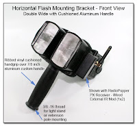
CP1104C (PJ1013B):
Horizontal Flash Mounting Bracket
Double Wide with
Cushioned Aluminum Handle). A 1x2 IR Emitter Cable and mod (as shown) for the Receiver Unit will cost $330. Additional 1x1 IR Emitter Cables are $60, while 1x2 IR Emitter Cables are $90. The Expansion Jack can be added for $75 if desired. The cable lengths can be altered to suit upon ordering, and both the Transmitter and Receiver Unit must be sent to me for the setup. Remember that this will void your warranty with the manufacturer.
 Here are 2 other types of Dual IR Emitter Cables: One has the Inline Splice and thus has the smaller molded RA sub-mini plug, in a similar setup to the Quad IR Emitter Cables, while the other one has the junction (and electronics) embedded in the assembled RA sub-mini plug. The Velcro Mounting Tabs are shown on this second cord only, but can be used for any of the IR Emitters.
(***) RadioPopper PX Ext IR Mod - Mtg Bracket NoGo
CP1104AD 11-16-11
 When the IR Sync Jack is added to the PX Receiver Unit (image left), the location is very specific based on the available space inside the current housing. The PX Mounting Bracket is not needed with this setup, as the foot of the PX Mounting Bracket will interfere with the insertion of the sync plug, as should be obvious in the image. The bracket can be modified to allow the sub-mini plug insertion for just an additional $10, but you do have to send the bracket along when you send the PX Receiver unit for the Sync Jack Mod. The PX Receiver unit can be attached using Velcro or gaffers tape, but not left to hang by the sync cord into the IR Sync Jack. You can also use the same type of rigid mounting as is used with the Fiber Optic Setup, as seen just below in item CP1104AE ($130).
(***) RP PX Ext IR Mod-Rigid FourSquare Mtg
CP1104AE 1-20-11
 This image shows the rigid mounting of the RadioPopper PX Receiver to the FourSquare Bracket. The Velcro Mounting Tabs (CP1104AF
CP1104AF:
IR Emitter-
Velcro Mounting Pads) are also shown being used on 2 of the 4 IR Emitters for the best way to reliably attach the IR Emitter over the IR Sensor of the flash unit. The Cinch Strap (PJ1091
PJ1091:
Safety Ring on Cinch Strap:
Quick and Easy Attachment Point or
Loop for a Safety Cable, with Nylon Tether) is usually better placed closer to the hinge joint, so it won't slip off the end of the flash head. The setup to mount the PX Receiver is $130, and the Velcro Mounting Tabs along with the Cinch Straps and Nylon Tether is $64 for a set of 4.
 In this example of the IR Emitter Splitter for the RadioPopper PX External IR Mod, you can see 8 IR LED Emitters, each on a separate length of thin (1mm) flexible cable, ready to be placed in view of a different flash IR sensor. The cables can be customized for length from 6 inches, to 6 feet, and any unused sensors can just be tied up and out of the way. These emitters on the thin cable are a little fussier to position on the flash unit than the upgraded version shown above using the heavier cable and sideways shining LED's.
(***) RadioPopper PX Ext IR Mod - Costs and Options:
This mod involves adding the sub-mini jack into the PX Reciever unit (technically for no charge), along with providing the Custom IR Splitter, which is $390 for a 1 x 4 split as shown using the = Heavy Duty (3mm) cables with the high output sideways shining LED's. Each additional pair of IR Emitters will add $90, so this 1 x 8 Splitter shown would be $390 + $90 + $90 = $570. An extra 1x4 IR Splitter Cable (in either the Inline format, or the Junction Box format), which has the Expansion Jack is $340, and naturally prevents the need to mod a second PX Receiver unit. The IR Splitter Cable sub-mini plug can either be the straight plug or the RA plug. The straight plug will fit nicer into the Expansion Jack while the RA plug will fit nicer into the new jack in the PX Receiver. A coiled rubber cable set is also available with or without the Expansion Jack, although this adds an additional $45 due to the difficulty of working with the rubber cables.
You do have to send me your PX Receiver and Transmitter unit for the mod and then testing, and as is the case with most all of the mods here, your manufacturers warranty becomes void upon the initial opening of the case.
This item has been both Canon and Nikon tested, and is easier to setup and operate than using the Fiber Optic Bundle Splitter Mods.
444444444444444444444444444444444444444444444444444444444444444444444444444444444
I2G(***) External Pickup Coil - RadioPopper PX
CP1104AG (2-13-2011)
The latest RadioPopper PX mod is for the PX Transmitter (image soon), and will add the sync jack to the PX Transmitter unit, and provide a new External Pickup Coil on a plug in cable, so that the PX Transmitter unit can be located separately from the unit itself. This is especially useful for the Nikon SU800 users, where the placement of the PX Transmitter unit will block the AF light, making it unusable. By relocating the PX Transmitter unit, the External Pickup Coil can be held in place using gaffers tape, or the optional Velcro Mounting Pad, which is similar to the Velcro Mounting Pad (CP1104AF
CP1104AF:
IR Emitter-
Velcro Mounting Pads) for the IR Emitters. The PX Transmitter unit itself can be secured using Velcro, gaffers tape, or one of my Cinch Strap, PJ1091
PJ1091:
Cinch Strap with Safety Ring:
Quick and Easy Attachment Point or
Loop for a Safety Cable, which prevents the need to gum up your flash plastic with the stick Velcro glue.
This External Pickup Coil on a short plug in cable for connection into the included sync jack mod in the PX Transmitter will cost $300. Separately, the Velcro Mounting Tab is $10, the Cinch Strap with Safety Ring is $12, but together they are $16 for the set.
************************************************************************
I2c(***) HFMB Double Wide with Aluminum Handle
CP1104C (PJ1013B)
Here is another mounting for the Double Wide HFMB, made for a photog wanting to easily hand hold a double flash in one hand, while shooting with the other hand. The Custom Cushioned Solid Aluminum Handle with the bottom 3/8-16 thread is $75, and the HFMB Double Wide Version is $60, for a total of $135 for this setup. The

 RadioPopper and flash units are not included in these costs, naturally. You can also have an Umbrella Hole and Thumbscrew added to this handle for an additional $25 (CP1104E
CP1104E:
Aluminum Handle and Cushion Grip
with Umbrella Hole and Thumbscrew
(10 Degree Angled)). Also seen in these photos is the RadioPopper PX Receiver which is firing the 2 flash units via the RadioPopper PX External IR Mod (CP1104B

CP1104B: RadioPopper PX
External IR Mod
1x2 Short Cable
with 2 LED Emitters).
 The image, left, shows a Screw Eye with a nylon Safety Strap attached to the Aluminum Handle, so the entire unit can be stored at any time by hanging it from the loop of the Belt Hook shown. With the Belt Hook on your left side (clipped onto your belt), the entire dual flash unit will then be ready at a moments notice for the left hand to lift the unit off the Belt Hook loop, raise the unit overhead, and direct the light where needed. This Screw Eye, Safety Strap, and Belt Hook adds $20 to the setup as shown ($40 if you want an all black Screw Eye and Belt Hook, image below). Loosen the hex nut, and remove the Screw Eye to gain access
 to the bottom 3/8 inch threaded hole for when you want to mount this Dual Flash Unit back on a light stand or extension pole. A threaded Reducing Bushing ($5 PJ1013a
PJ1013a: Spigot
Conversion Bushing
and Threaded Studs
3/8 and 1/4 inch) will allow 1/4 inch accessories to be threaded into this larger 3/8 inch threaded hole.
 The Aluminum Handle & Cushion Grip can have the Umbrella Hole and Thumbnut added as shown (assembled view). In this case, the hole is drilled at a 10 degree up angle (or any other angle you choose), and adds $25 to the setup. The hole is sized for a 3/8 inch umbrella shaft, but can be
  enlarged if needed. This handle has threaded mounting holes in the top for the HFMB, and a 3/8-16 thread in the bottom for the Screw Eye and Safety Strap or for attaching this handle to a light stand or extension pole.
This handle can be ordered as a stand alone item for $100 (CP1104E), and then there will be a 1/4-20 threaded hole in the top for mounting acessories, as well as the 3/8-16 threaded hole in the bottom for connection to a light stand, extension pole, or anything else you can think of. If you prefer a different threaded hole arrangement, just let me know, and I'll see what I can do.
I2d(***) HFMB w/ Umb Adapter & Handle (12-19-10)
CP1104G
 Here is another version of the HFMB w/ Cushioned Handle. An Umbrella Adapter Block has been machined from the same tough, rigid, impact resistant material as the HFMB itself: acrylonnitrile-butadiene-styrene (also known as ABS for short). The Umbrella Adapter Block is the full width of the HFMB, so the umbrella hole is longer than usually found in most umbrella adapters, and allows 2 nylon thumbscrews to be used for securing the umbrella
  shaft. The bottom of the Umbrella Adapter Block is threaded with a 3/8-16 thread (see image left, and another nylon thumbscrew provides cross locking on any 3/8-16 threaded stud inserted in this bottom hole. A male spigot can be directly threaded into this hole, or a 3/4 inch threaded stud can be provided ($5) to allow a female spigot to be threaded into this hole. The Umbrella Adapter Block will also allow the HFMB to be directly connected to a monopod with or without an angle adapter, as seen in the Dual Flash section (DF1026).
The Cushioned Aluminum Handle has 3/8-16 threaded holes in both ends, and a threaded stud is shown in the top end, locked in place by the flush set screw, ready to be threaded into the bottom of the Umbrella Adapter Block to provide an easy and comfortable to hold dual lighting bracket. The Screw Eye, and Belt Hook provide an easy way to let this dual lighting setup hang on your left side, ready for action when needed.
Because of the thickness of the rubber cushion handle bottom, an extra long 3/8-16 bolt is needed when attaching a Monopod Tilt Head like the Manfrotto 234 into the bottom threaded hole. See the Monopod Tilt Head w/ Custom 3/8-16 Bolt (PJ1094
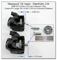
PJ1094:
Monopod Tilt Head
Manfroto 234 OEM vs
Custom Longer 3/8-16 Bolt).
Flash Trigger Notes:
This Dual Flash Setup can be fired in several ways, tethered or wireless. Shown just above, the RadioPopper PX units can trigger these flash units in a Wireless Wired IR Splitter (CP1104AC) or Wireless Fiber Optic fashion (CP1027), or a Pocket Wizard FlexTT5 unit can fire the 2 flash units by using the Dual Linked OC-E3 setup (PJ1087). You can even shoot completely in manual mode, but ththered using a Dual Linked Sync Cord that splits for each flash unit, and will have only a single coiled or straight cable going back to the camera for sync. If you are unclear on any of these setups, please ask! (Additional links to these different firing methods coming soon!)
(***) Costs: HFMB Double Wide w/ Umb Adapter and Cushioned Aluminum Handle Setup (CP1104G

CP1104G:
Horizontal Flash Mounting Bracket
Double Wide with ABS Umbrella Adapter Block
Cushioned Aluminum Handle
Powder Coated Screw Eye, and Belt Hook)
The HFMB Double Wide Version with the Umbrella Adapter Block attached is $120, while the Cushioned Aluminum Handle, threaded stud and setscrew is $100, and the Screw Eye and Belt Clip (black) is $40, for a total of $260 for this setup.
I2e(***) HFMB Medium Wide for Lastolite EZYBox w/
Reinforced Riser Block
CP1104H (PJ1001A) 1-26-11
 This Horiz Flash Mtg Bracket (HFMB) is a specialized Medium size of the normal HFMB (larger than the Single Wide [PJ1001
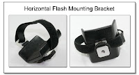
PJ1001: Horizontal Flash Mounting Bracket], smaller than the Double Wide [PJ1011
PJ1101: Double Wide Horizontal
Flash Bracket - Front/Side View] versions), in that it allows the flash to be held in a flat, horizontal orientation, especially for use with the Lastolite EZYBox Mark II Bracket

HFMB Medium Wide for
Lastolite EZYBox
Mark II Bracket (image just below), or any other bracket you choose. This HFMB can be ordered with the normal spigot, locking foot, or umbrella adapter, just as both the
 single and double wide versions can, or it can be ordered with the Reinforced Riser Block shown in these images. Flat head stainless steel machine screws (4 in total) travel the full length of the setup from under the foam pad to the locking foot mount to increase the rigidity of the
  setup having such a long moment arm. The flash body can easily be rotated 90 degrees if desired (left image of composite) so the FlexTT5 antenna points upward, or the display is easier to see. The Safety Ring makes for an easy place to attach the nylon tether (if desired). The image just above shows the range of flash mounting limits using a Nikon SB900, although most often the flash head will naturally be centered in the opening of the Lastolite EZYBox Mark II Bracket.
The Reinforced Riser Block (2.375 inches high, just above), attached with the flat head stainless steel tension screws to the standard locking foot, will add $60 to the base cost of the HFMB for a total cost of $115. A custom sized Reinforced Riser Block can also be fabricated based on your specifications for another type of bracket not shown, just ask.

 Shown in these images (left, right) is the Lastolite EZYBox Mounting Ring and Bracket (original version) that is made of metal. The inner opening is circular, not rectangular as in the newer Mark II plastic version. By turning the metal angle bracket so it is pointing downwards, and replacing the thumbscrew that holds this angle bracket to the vertical support with a low profile 0.5 inch long thumbscrew ($5), the normal sized HFMB (with the Standard Locking Foot, $40) can be used to hold just about any small flash unit. For even extra adjustment capability, you can have the HFMB made in a Double Long Version with the reinforcing plate, and double Cinch Straps for an additional $40.
 The HFMB Dbl Wide, Rotating Speedring Mount (PJ1104
PJ1104:
Horizontal Flash Mounting Bracket
(HFMB Dbl Wide), Rigid Umbrella Riser,
Chimera Speedring,
Axial Rotation Bracket,
Spigot Mounting (top view)), makes use of some new components to mount 2 flash units with a center line umbrella mount, as well as mounting to a speedring and allowing axial rotation of the setup from a single mounting point (also see PJ1102

PJ1102:
Horizontal Flash Mounting Bracket
(HFMB Dbl Wide),
Rigid Umbrella Riser, Spigot Mount, PJ1103
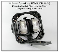
PJ1103:
Horizontal Flash Mounting Bracket
(HFMB Dbl Wide), Extension Bracket,
Rigid Umbrella Riser, Spigot Mounting,
Front View).
I2f(***) HFMB Medium Wide for Horizontal Format:
Quantum Trio, Canon, Nikon & Others
CP1104H (PJ1001A) 8-24-11
 The HFMB Medium Wide Version is $55 including any of the 3 Foam Spacer Pads, and attached to the spigot or standard locking foot. An attached Umbrella Adapter adds $30.
 In this image left, the 1/2 inch Foam Spacer Pad is being used to take up some of the slack in the Cinch Strap, and provide extra cushioning for the top surface of the flash. The size of this HFMB, along with one of the Foam Spacer Pads, will also make for a secure mounting for the Quantum QFlash Trio, as well as many other flash units with a flat horizontal dimension of up to 3 inches.
  This image, sent in by Peter at Life Moments Photography of Scottsdale, AZ, shows the QFlash Trio mounted in the HFMB (Medium Wide), using the 1/2 inch Foam Spacer Pad both for added support, and to help take up the slack in the Cinch Strap. The metal ring provides an easy attachment point for a safety strap tether.
I3(***) RadioPopper Dual Fiber Optic Bundle Mod
CP1034
 If you shoot with a Dual Flash Setup of any kind, and are also using the RadioPoppers P1 series, the Dual Fiber Optic Bundle Mod is something you will need. Each separate bundle will get about 90% of the signal light, and will fit into the access port of the case without modification (Countersink is suggested), so the there should be no problem sending the optic signal to the 2 flash units. This Dual Fiber Optic Bundle Mod is $40 plus the cost of 2 single fiber optic bundles drop shipped to me directly from RadioPopper (my full address is on the title page, above). I have access to this same 3 mm fiber optic cable, so cables longer than the standard 7 inches are available, although the clear vinyl reflector end must still be secured from RadioPopper directly.
J(***) RadioPopper Countersink of Access Port - DIY
CP1035
 To make it easier to insert the Fiber Optic Bundles, original or Dual Bundle (above), you should countersink the opening of the plastic case, SLIGHTLY. This is done by GENTLY rotating (by hand) a drill bit or countersink in the access port of the case to remove the sharp edge of the plastic case. This countersink area will resemble a funnel, and will not only make it easier to insert the fiber optic bundle through the case into the internal guide tube, but will prevent causing a knick in the outer jacket of the bundle, and will also prevent stress points on the bundle when bent upon exiting the access port.
K(***) RadioPopper Dual Pickup Coil
CP1036
 The Dual Pickup Coil Mod for the RadioPopper Transmitter puts an additional pickup coil inside the plastic case at the bottom front corner, in the location indicated by the white label in the image. The little slide switch is used to control which Pickup Coil is active. This will allow different mounting positions of the RadioPopper, such as on the narrow edge, sitting next to a PW, and both units sitting on a ST-E2 control unit, as can be seen just below (image coming soon). The price for this mod is $80, and like most of my other mods, this will take just a day or so, but will naturally void the manufacturers warranty for this item.
L(***) RadioPopper Extension Pickup Coil Mod
CP1037
 Sometimes the RadioPopper Pickup Coil is just not in the best place when you are trying to mount the unit, so the Extension Pickup Coil Mod will allow placemnt of the Pickup Coil pretty much anywhere you wish at the end of the 6 inch cable. The coil and connections are encased in an epoxy shell for protection, and the cable stores back in the case through the slot near the original position of the coil (see enlarged inset image here). The price for this mod is $80, and like most of my other mods, this will take just a day or so, but will naturally void the manufacturers warranty for this item.
M(***) Custom Combo Unit
CP1038
 The Combo Unit consists of 3 modified units: the ST-E2 (Aux Sync Jack, Metal Foot), RadioPopper (Dual Pickup Coil, Extension Pickup Coil), and a Pocket Wizard (PW Removable Antenna Mod), all attached to make it as one self contained secure unit. This setup was done by brainstorming with a photog based on his shooting style needing many options in a very secure, small package. Suggested in the image text, and done before delivery, was to remove the foot of the Pocket Wizard, and close the opening to make an even smaller profile, since it was determined that the Combo Unit would likely remain as a dedicated unit, and only need to be taken apart to change the batteries.
N(***) iPhone Breakout Cable
CP1039
 The iPhone Breakout Cable is a Custom Headset Pass Through Cable, with a "Breakout Jack" which allows access to the speaker and microphone audio when using a headset with the iPhone. This is NOT a conventional "2 way splitter cable" (which is shown in the next image below). The "Breakout Jack" can be connected to a 2 channel (stereo) recorder to record both the send and receive sides of the iPhone conversation, OR an audio source can be input through this "Breakout Jack" to broadcast over the iPhone instead of
  speaking into the microphone. The iPhone Breakout Cable uses a special 4 conductor mini plug to fit into the mini jack at the top of the iPhone (Blackberry, and even the Droid). The extra skinny neck will fit into the recess of the original iPhone, as well as the newer iPhones. This iPhone Breakout Cable is $95 as shown in the first image, or $115 in the second image that includes the Y Splitter (4 ended cable), although any number of custom setups are available, and as most things on this site, are only limited by your imagination. Custom and stock cables are available to connect the "Breakout Jack" to the specific inputs of your recorder, just ask!
Update:
This IPhone Breakout Cable will work with the Blackberry devices also.
Connections:
Since the unamplified mic audio signal is about 10 times weaker than the headset audio, the Breakout Cable must be plugged into the MIC input or your recorder. If you connect the Breakout Cable to a LINE IN port of the recorder you will hear the proper level of the headset audio, but the mic audio will be muted. Smaller recorders will have an Auto Gain Control (AGC) so the headset audio will not overpower the MIC input, while bigger recorders will have adjustable levels for each channel input.
2 Channel vs 1 Channel Recording:
Remember, that this device is specifically made to output the headset audio on one channel, and the mic audio on a second channel for 2 channel recording (with music recording, this is commonly called stereo recording). With each part of the conversation on a different channel, or track, specific file manipulation is possible.
Two channel recording is useful to isolate either the headset audio, or the mic audio, as a single channel recording of a duplex conversation will allow one voice to be recorded over another voice (as when both parties are talking at the same time). This is like shooting an image in "RAW" as opposed to "JPEG".
Two Channel recording will use up twice as much tape or memory than one channel recording, and thus one channel recording can be 2 times as long for a given storage medium.
2 Channel Combination Pre-Recording:
If you are wanting to combine the mic audio and headset audio prior to recording, so that the entire conversation can be recorded onto a single channel as one, then you will need to run both channels through an electronic combiner first, like this Cell Phone Recording Combiner, which is made for non-iPhone cell phones, or the Cell Phone Recording Combiner - iPhone Version. The mic input volume can be adjusted (attenuated) by using the Cell Phone Microphone Volume Control, which can be made as a stand alone unit, or incorporated into a combined custom mixer unit.
2 Channel Combination Post-Recording:
If you want to combine the mic audio and headset audio post recording, as if to moniter the recording through a single earphone, or to output the recording to another device for upload, you need to use a stereo to mono adapter cable plugged into the output of your recorder. This item can be made to your specs depending on what you are trying to connect.
Legal Notice:
This recording device can only be used where legally allowed and with proper notification of the parties involved.
P(***) 4 Conductor Y Splitter / Conversion Cable
CP1041
 This image shows a 4 conductor Y Splitter which is $75, and a Custom Conversion Cable for $75 that would plug into one leg of the Y splitter to make this setup into a breakout jack with headset pass through. These 2 items are only sold as a set. Again, specific connection cables to suit your needs based on your specific recorder, are only limited by your imagination! (This device can only be used where legally allowed and with proper notification of the parties involved.)
P1(***) Cell Headset to Computer Audio Adapter
CP1042
 This Cell Phone Headset Adapter will allow you to connect your 3.5mm or (2.5mm headset) to your computer Mic and Audio inputs. This way you can use the headset you already have from your cell phone to listen and even talk into your computer for Skype, watching a DVD, or just listening to music. This item is $75, for either the 3.5mm stereo headset, or the 2.5 mono headset (please specify) and is usually made about 4 inches long.
Q(***) Cell Phone Recording (non iPhone)
CP1043
 The Cell Phone Recording Combiner (non-iPhone) will allow the recording of both sides of a cell phone conversation and combine the mic audio and the headset audio into a single channel for use in many analog and digital recording devices. This version is has a 2.5mm input jack for your standard 2.5mm cell phone headset (non-iPhone), and a 3.5mm output (6 inches) to connect into a recording device, and a 2.5mm output (6 inches) to connect into your cell phone as the headset pass though connection. This item is $195 as shown (headset available, but not included).
R(***) Cell Phone Recording - Long Leads
CP1044
 This image shows the same Standard version with the longer output cables. Any of the output or input cables of this version can be made up to 66 inches long for just an additional $25.
See also the iPhone, and the Blackberry versions of the combiner.
The electronics in all the versions are set for a fixed volume level ratio between the mic audio and the headset audio, although an option is to add a Custom Balance Control. Another option is for Two Channel Recording; the ability to either record the mic audio and the headset audio onto 2 separate channels or to record onto a single channel. Two channel recording is useful to isolate either the headset audio, or the mic audio, as a single channel recording of a duplex conversation will allow one voice to be recorded over another voice (as when both parties are talking at the same time). (advanced version images coming soon).
S(***) Cell Phone Recording Combiner (iPhone)
CP1044a
 Recording from the iPhone: The iPhone Breakout Cable is needed in addition to this special version of the Cell Phone Recording Combiner - iPhone Version and will allow the recording of both sides of a cell phone conversation and combine the mic audio and the headset audio into a single channel for use in many analog and digital recording devices. This version is has a 3.5mm input jack for connection to the iPhone Breakout Cable, and a 3.5mm output (6 inches) to connect into a recording device for one channel recording. This item is priced at $175. The electronics in this version are set for a fixed volume level between the mic audio and the headset audio, although an option is to add a Custom Balance Control. The output cable lengths can be made up to 66 inches long for just an additional $25.
See also the Standard Cell, and the Blackberry versions of the combiner.
T(***) Cell Phone Recording - Long Leads - Blackberry
CP1045
 This image shows a setup of the Recording Combiner Box - Blackberry version. As you can see the input jack is not mounted into the box as the models above, but instead is mounted to a length of cable, based on the specific customers needs. This will allow the recorder and cell phone to be put off to the side, and the headset then connects directly to this input via the single cable. These Blackberry versions use a more difficult to find 4 conductor input and output, and as pictured, is $195. An extra INPUT cable can be added for $75 to allow a second headset to become part of the conversation, and an extra OUTPUT cable can be added for $65 if 2 channel recording is desired on certain occasions. Why would you want 2 channel recording, as opposed to one channel recording? It is discussed in greater detail in the section above for the iPhone Breakout Cable, but with duplex communications, both parties can talk at the same time, and listening to the recording, it would be easy to not understand what is being said. If the mic audio is recorded separately from the headset audio, it becomes a simple matter to listen to one side of the conversation, or the other, without the overtalk.
See also the iPhone, and the Standard Cell versions of the combiner.
Legal Notice:
These recording devices can only be used where legally allowed and with proper notification of the parties involved.
U(***) Cell Phone Microphone Volume Control
CP1046
 If you are using your wired headset to record or transmit from a very loud environment, you might need this Cell Phone Microphone Volume Control. This is a passive device (no batteries), and this version will plug into a standard cell phone (2.5mm plug/jack), and allow the wired headset to plug into this device. The microphone input volume can then be dialed down (attenuated), so that the other party, or recorded track will not sound distorted from the volume being too loud. This standard cell phone version is $165, and versions for the iPhone and Blackberry are $180. (The iPhone and Blackberry versions use a straight 4 conductor mini plug, and a 4 conductor mini jack.) Each of these Microphone Volume Controls, can also be added into the Recording Combiners above, although a slightly larger control box will be needed.
Custom miniature mixers, both passive and active, can also be made directly to your specifications, as a way of modifying pre-recorded inputs. The hardest part is to define the problem...
V(***) Custom Adapter - Mount Slave to Trigger PW
CP1047
 Here is the Custom Adapter for Mounting an Optical Slave Trigger to a PW (see inset). The PW shown is attached to the flash head using a simple bracket called the PW Caddy ($16 each) which eliminates the need for Velcro, elastics, or tape. Plugged into the input of the PW is the Custom Adapter which puts the Sonia Optical Slave Trigger in view of the flash unit. When the flash fires (manual Mode), the optical slave unit will trigger the PW to transmit a signal. The
 Custom Adapter is $40, and the Sonia Optical Trigger is $20. This is especially helpful in that no cord is needed to connect the PW to the flash or camera in order to transmit a signal to remote off camera flash units being fired by PW receivers. The transmit signal works even if any of the translucent diffusers are placed over the end of the flash unit.
IMPORTANT NOTE: Remember that the flash that is setting off the optical slave must not fire a pre-flash, which is why manual mode is often needed. If you want this same setup, but want to use this flash in eTTL mode, then the PW must be triggered by either connecting to the camera PC port, or through the Aux Sync Jack of the flash unit.
A new unit in the works is a Pre-Flash Ignore Trigger, which will only fire the radio transmitter when the main flash fires, and not on any of the pre-flash activities.
W(***) Short RA-RA Sync Cord
CP1049
The images below (click to enlarge in a new window) show how a shortened RA-RA sync cord (10.5 inches seems to be best) is used to neatly connect a PW (mounted on a PW Caddy) to a flash unit that has the Aux Sync Jack added. The cord allows full rotation of the

 flash head, but is not so long that it gets in the way. This sync cord is $20 by itself, or just $5 when the Aux Sync Jack Mod is done on your flash unit. The PW Caddy is available for $16 each.
X(***) Special Cables for Canon EX Trigger
CP1051
 This image shows the different Sonia Optical Trigger Connection Options for use with the Canon EX Flash Units. Who said the Canon EX flash units (580 EX, 550 EX, 430 EX) don't work with the Sonia Optical Slave Trigger (sold here for $25)? I have added the electronics into several devices (hot shoe, connectors, etc) for easy to use, repeatable results (without having to unplug the unit after every flash). The standard Kaiser Hot Shoe (similar to #3) and also seen throughout the Hot Shoe Section of my site, can have the electronics added for $55, in addition to the cost of the specific hot shoe and options chosen. Each of the other cables and adapters shown here are just $50. Items #1 and #2 have an inline mini jack to connect directly to the standard hot shoe to mini plug adapter, and thus provide the Optical Trigger Connection and allow mounting of the Sonia Optical Trigger, either to be attached to the top of the flash unit with Velcro, tape, or elastic. In the images below, the
 image on the left shows the Special Mini Plug to PC Jack Cable attached to the standard Hot Shoe to Mini Plug Adapter (item #1 in Connection Options, above - click to open image in a new window), while the right image shows the Special RA Sub-Mini Plug to PC Plug Cable (item #5 in Connection Options, above), connected directly into the Aux Sync Jack of the 580 EX unit.
Items #4 (a,b,c) (Connection Options, above) are different configurations of a rigid attachment shown in the sub-mini plug format (mini plug available upon request). The Inline version (#4a)
 is shown is the image here, and they all can be swiveled from front to back to better "see" the incoming flash. Each of these adapters will connect directly into the Aux Sync Jack Mod I do for all the Canon EX (and other) flash units. Item #5 ends in a sub-mini plug like item #4 to fit the Aux Sync Jack, while item #6 ends in a mini plug to fit those added sync ports where the mini jack has been used. When the Optical Trigger is on a corded device like items #1, #5, or # 6, it is usually easier to keep it in the "view" of the incoming flash, while the adapter #4 is more compact, but less flexible in the placement.
Y(***) Special Sync for Optical Trigger of Canon EX
CP1055
 Here is a newer version of item # 4b where the offset is only 0.75 inches. This can also be made as in item # 4c, with both plugs on the same side, and the cost is still $50 just like all the other Special Sync Cables.
Z(***) Special Sync Cable - PC Jack-PC Plug
CP1056
 Here is the Special PC Jack to PC Plug Cable, which is $55, and is actually a short PC extension cable with the built-in electronics to make the Sonia Optical Trigger ($25) work (repeatedly) with the EX Flash units. The PC jack will connect to the PC plug at the end of a standard Hot Shoe Adapter (item C and H) and available at just about any camera shop or online.
AA(***) Special Sync Cable - PC Plug-PC Plug
CP1057
 The Special Sync Cable (PC Plug to PC Plug) is similar to the Special PC Jack to PC Plug Cable (above), except that instead of being an extension cable, it has a PC plug on each end. This cable is also $55. This PC plug can connect to one of the flash mounting adapters that have a PC jack as in item F) here, and in this image. To have one end of this cable end in the Screwlock PC Plug (not shown), instead of the standard PC Plug (as shown), is $60.
Note: The Sonia Optical Trigger along with one of these Special Cables will fire the Canon EX flash repeatedly when in eTTL mode with the flash in the wireless settings of OFF, MASTER (580EX, 550EX), or SLAVE, and when the flash is in MANUAL mode, it works with the wireless settings of OFF, and SLAVE.
AB(***) RA Plug - Nikon D70s, D80
CP1058
 This is a Custom RA Plug for the Nikon D70s and D80 made from the standard straight plug shown on the left is $145 including the hand controller ($135 without the controller). The cable can be made to point up or down. Add in a mini-plug / mini jack disconnect in the line for $75 additional.
AC(***) RA (UP) Plug - Nikon D70s, D80
CP1059
 This Custom RA (UP) Plug (see inset picture) for the Nikon D70s and D80 is also made from the standard straight plug and is $135 for the plug mod itself, and then $75 for the mini jack / mini plug disconnect. The wire here will point upwards, and the Safety Clip is also included as a way to secure the cord, prevent pullout, and allow for a quick disconnect. (The Gadget Infinity wireless remote is not included.)
AD(***) RA (UP) Plug (Snug Fit) - Nikon D70s, D80
CP1060
 The Custom RA (UP) Snug Fit Plug is shorter and fits closer into the D80 socket than the connector shown above. Like the other re-molded plugs, it is $135 for the plug mod itself, and then an additional $75 for the disconnect, and $10 for the hand controller.
AD1(***) RA (Forward) Plug - Nikon D70s, D80
CP1061
 This Custom RA Plug (Forward) for the Nikon D80 points towards the front of the lens and was made to get the smallest size possible starting with a standard D80 connector. It is just under 19 mm from the tip of the metal connector to the back edge of the molding. As in the other versions of this mod above, it is $135 for the plug mod itself, and an additional $35 to include the generic hand controller. The mini jack / mini plug disconnect can be added for $75.
AE(***) RA (Forward) Plug - Nikon D90
CP1062
 The Nikon D90 uses a different plug than the Nikon D80, and here is the plug from the MC-DC2 Remote made into a Custom RA Plug (Forward). Currently this re-molding mod is $135, (plus the cost of the plug and hand controller itself), and the best plug to use for this mod is the true Nikon version, although it is more costly than the generic versions of the D90 plug. This image shows the RA angle facing Forward when the plug is inserted into the camera, but any other direction can also be done for the same cost if needed. The indicated size of 0.88 inches (maximum) overall length was set for a specific custom application for this camera and plug to fit within a watertight, submersible camera pod. Most of the current batch of plugs are from 0.825 to 0.850 inches in length.
Nikon D7000 Update (1-30-11) The Nikon D7000 uses this same MC-DC2 plug (see comparison image), but the connector will need to be bent 90 degrees opposite to the image for it to be called
 "Forward". If you are unclear, look at the image (just above) for the little notch in bottom of the large flat face of the plug. The finished plug for the D7000 will look the same, except the notch will be on the outside of the 90 degree angle, as opposed to the inside of the 90 degree angle. On the D90 camera left side (see comparison image), this notch is facing forward, while on the D7000 camera left side, this notch is facing towards the back of the camera.
(***) Re-Mold MC-DC2 / Adapter Cable / L-bracket
CP1117 7-17-2014


Re-Mold MC-DC2 / HD Multi-Pole Disconnect
 Another option would be to use a Heavy Duty Multi-Pole Disconnect as shown. Each Multi-Pole connector is $55, in addition to the adapter cable for $35, and the MC-DC2 Re-Molding for $135. A Safety Clip ($5) can be added as well to secure the Adapter Cable to the camera strap attachment point.
 Here the MC-DC2 Re-Mold is oriented "down" as this unit was made for the Nikon D750 where the connection point is towards the upper side of the camera, just opposite that of the D7100. When used with most L-Brackets, the Mini Disconnect and Flat Cable can pass between the L-Bracket and the camera without too much difficulty, and without having to loosen or remove the
 entire L-Bracket. If a notch does need to be filed in the L-Bracket, it can then be made even smaller than with a conventionally sized cable. Shown attached to the end of the Flat Cable is a sub-mini (2.5 mm) inline jack, so that a standard unmodified hand controller like a Canon RS-60E3 can be used. In the second image (closeup of the MC-DC2 Plug Re-Mold), the new smaller overall size can be seen. The MC-DC2 Re-Mold is $135, the Flat Cable, MC-DC2 plug and Mini Disconnect is $75, and the sub-mini (2.5 mm) jack will add $10. Many other interconnects can be used instead of the sub-mini inline jack, if desired (just ask).
CP1117

CP1117
Re-Molded MC-DC2 Plug
Adapter Cable with
L-Bracket---Re-Molded MC-DC2 / Adapter Cable / L-Bracket 7-17-2014
CP1117

CP1117
Re-Molded MC-DC2 Plug
Flat Cable
Mini Disconnect---Re-Molded MC-DC2 / Flat Cable / Mini Disconnect 12-1-2014
AF(***) Custom Nikon 10 Pin Re-Mold
CP1063
 Here is another of the custom re-moldings: the Nikon 10 Pin Re-Molded Plug. Comparing the OEM vs the Re-Molded plug, you can see they are just about the same size, but the Re-Molding allows the strain relief and the cable to fit closer to the camera body without sticking out to the side. There is not as much finger room next to the camera body as in the OEM version, so tightening the locking ring is a bit more difficult. The same Re-Molding can be done with the generic friction fit 10 pin plugs, and these have no locking ring to tighten. The Re-Molding mod is $135, not including the 10 pin plug. This OEM plug is usually $45, but if the Re-Mold Mod is done, the OEM 10 pin plug (on a length of cable up to 24 inches) would be $35.
 This Nikon 10 Pin Re-Molding has an attached mini jack which is directed vertically downwards. It is about 2.875 inches from the center of the 10 pin to the end of the mini jack, as it works best when there is a short flexible section to allow for some movement in the
 cable. If you use a battery grip, then you might want this length about an inch or so longer so as to clear the front edge of the battery grip. Once the locking collar of the 10 pin connector is screwed into place into the camera connector, this becomes a semi-permanent connection point, and allows a quick and easy connect or disconnect of the trigger cable. The RA mini plug / inline mini jack disconnect adds $75, the Re-Molding is $135, not including the MC-30 or other hand controller. The Soft Vinyl cover ($5) will provide some degree of weather protection from the elements.
AG(***) Aux Collar for Nikon 10 Pin Plug
CP1064 (PT1014)
 This Aux Collar for the Nikon 10 pin plug is a custom, press fit, 0.75 inch diameter, knurled plastic collar which makes it easier to turn the metal collar, especially in tight spaces, when wearing gloves, or for extra large fingers. The image left shows the Aux Collar on a
 Nikon 10 pin plug in a D300, showing the clearance to the lens release button, and the PC jack. As each collar is custom made and fit, the specific cable does need to be sent to me, or this item can be fit to a new plug end on a new device. This Aux Collar is currently $25 each. This same item is also made for the ScrewLock PC plug and can be seen here as item SC1003
SC1003: Aux Collar on
ScrewLock PC Plug.
Another mod for the Nikon 10 pin plug is the Custom Re-Mold of the plug itself so the cable exits in a more downward direction, as opposed to sticking out from the camera body, as seen in the Custom Nikon 10 Pin Re-Mold (CP1063

CP1063:
Nikon 10 Pin Plug
ReMolded for Closer Fit
to Camera Body).
AH(***) Re-Molded FireWire Plug (UP)
CP1066
 Here is a Re-Molded FireWire Plug (RA UP facing) to make the cable fit closer to the body of cameras like the Canon 1Ds. The Re-Molding is $135 plus the cost of the cable, which is usually about $35.
 A closeup of the new re-molded plug can be seen in this image.
The direction of the Re-Molding can be customized to suit your specific camera (send me an image of the FireWire jack on the side of the device for true confirmation of the clearances).
 This FireWire Port Extension has the cable exit at a slight forward facing angle (for the Canon 1D series, and others) so it will not obstruct any other ports on the side of the camera. It has a low profile and doesn't stick out very much from the camera body, especially useful when shooting tethered to a computer. A Safety Clip is included to attach to the camera strap mounting ring, and the close fitting overmold has enough bulk, but is still a small enough profile to make it easy to grip, but hard to knock out of place. This is truly a custom mod, and you can actually specify which direction and angle you would like the cable to exit from the housing. This Custom FireWire Port Extension Cable is $105 and seems to work best at about 12 inches long (even though the image shows a shorter cable), with the cable exiting in any direction. A FireWire Cable connected to the free end of this Port Extension will provide an axially aligned disconnect that will minimize the stress and strain on the FireWire port of the camera. Scroll down just past the Mini-USB Port Extension to see available FireWire cables in 10, 15, and 25 foot lengths.
AI(***) Mini-USB Port Extension
CP1069
 This Mini-USB Port Extension has a low profile RA molding so it doesn't stick out very far from the camera body. This is especially good for shooting while tethered to a computer. For the Canon 5D (image below), XT series, and other models where the mini-USB port is oriented vertically with the longer side towards the front of the camera, this angled exit of the cable will point downwards and just slightly backwards to bypass other camera ports and stay clear of the photogs face. The 12 inch cable length has a Safety Clip for
  attachment to the camera strap mounting ring as can be seen in this image as the cable is connected to a Canon 5D camera. Connect an Extension Cable to the free end to provide an axially aligned disconnect that will minimize the stress and strain on the camera mini-USB port. This Custom Mini-USB Port Re-Molded Extension Cable is $170, and can be made as shown, or with the cable exit facing UPWARDS and FORWARDS as in the shorter version below, or any other direction you wish.
AJ(***) Mini-USB Port Extension - Canon XT
CP1071
 This same Mini-USB Port Extension Cable is shown (click to enlarge) on a Canon XT (350D) camera. Again, the Down Angle remains clear of the face when attached during tethered shooting. Since there are no other ports lower than the mini-USB port, the offset bend is not as necessary as it is for a camera like the Canon 5D.
AK(***) Mini-USB Port Extension (UP/Forward)
CP1072
 This Mini-USB Port Extension also has a low profile RA molding, but the cable exit is UPWARDS and FORWARD. The short (approximately 6 inch) cable length has a Safety Clip for attachment to the camera strap mounting ring, but the rubber weather cover does get in the way in this configuration. Connect an Extension Cable to the free end to provide an axially aligned disconnect that will minimize the stress and strain on the camera mini-USB port. This Custom Mini-USB Port Extension Cable is $170, and can be made as shown, or with any other cable exit direction you wish.
Coming next: Mini-USB Port Extension for horizontal oriented port.
(***) USB & Mini DisplayPort Re-Mold 20 Deg Offset
CP1072A (8-28-11)
 These cable Re-Molds are for one of the new Apple MacBook Pro laptops. The Re-Molding mod is $135 each, not including the cost of the starting cable, which can be sent to me, or I can secure for you based on your needs.
AL(***) USB UltraFlex / FireWire Extension Cables
CP1073
A USB UltraFlex Extension Cable (M/F) with a covered boot in a length of 10 feet is available here for $25, while the 6 foot version is $20 and a 3 foot version is $15. The FireWire 4 Pin Cable (M/M) is available in a 15 foot cable for $35, a 10 foot cable for $25, a 6 foot cable for $20, a 3 foot cable for $15, and a special 25 foot heavy duty cable (not shown) for $45 as in the 2 images below (click either to enlarge):


AM(***) Custom Double Hot Shoe
CP1075
 The Custom Double Hot Shoe was first made for a Leica owner where the original placement of the camera hot shoe interfered with a special finder the photog wanted to use. The starting unit is a Voigtlander Double Shoe Adapter that has no electrical contacts, and then gets turned into one or two new hot shoes. As shown with one cold shoe turned hot the mod fee is $110. For the second shoe to also be hot would add $50. The mod can be done on a Voigtlander Double Shoe Adapter that you send me, or have one drop shipped to me from your supplier. The base item (double cold shoe bracket) has been discontinued from the manufacturer for some time now, so this can only be made if you already have this base item to send to me for the mod.
AN(***) Custom Double hot Shoe (B version)
CP1076
 This Custom Double Hot Shoe is made using the "B" version, and has a Voltage Limiter Module installed on the underside. The starting unit is a Voigtlander Double Shoe Adapter that has no electrical contacts, and then gets turned into one or two new hot shoes. As shown with one cold shoe turned hot the mod fee is $110. For the second shoe to also be hot would add $50. This custom module can be installed almost anywhere, in any space, and will limit the trigger voltage to less than 6 volts. The Voltage Limiter Module is an additional $50 for most projects, or by quote depending on the customization.
 Note: This item was originally made in the minimal height shown, the "A" size, and 2 other versions, the "B", and "C" heights. All 3 versions have been discontinued, although there may be some "C" units still available.
Click here for an example where the Voltage Limiter Module has been added into the Replacement Foot Assembly for the high trigger voltage Vivitar 283 flash unit. The possibilities are almost endless!
AO(***) Low Profile Hot Shoe Pickup
HS1010 (CP1077)
 The Low Profile Hot Shoe Pickup shown here, ending in a sub-mini (or a mini plug) and is $185. It was first made for some Leica owners to provide an off camera flash connection in a limited height format. Mini or sub-mini extensions are also available to extend the reach in lengths up to 100 feet. The Kaiser Hot Shoe can have a sub-mini Aux Sync Jack added, and supplied with a standard sync cord or connection to any other device. The Hot Shoe with the sub-mini aux sync jack and a standard sync cord 16 inches, RA sub-mini plug to a straight mini plug is also $145. Use a "Barrel Connector" (SC1045
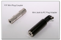
SC1045: Mini Plug Coupler (left image)
Also called "barrel" or
"gender changer") to act as a "gender changer" to connect the mini plug end to another mini plug for just $15. The Mini Jack to PC Jack Adapter Cable (CP1030A

HS1010C: Adapter Sync Cable
Mini Jack to PC Jack), shown also just below for $35 will convert the standard mini plug end to allow connection to a standard PC plug.
 Here is another view of the Low Profile Hot Shoe Pickup, and you can see that the overall height from the top surface of the brass cap to the bottom surface of the contact button is just 7.40 mm which is less than the 7.68 mm that is available under the Visoflex prism when used in the Leica setup. The other dimension that is critical in the Leica setup is seen in the next image below, and that is the overall
  height above the top surface of the camera hot shoe rails, which is shown as 3.41 mm. This dimension will vary somwhat depending on how tight the brass cap is screwed down, and the specific physical size of the individual hot shoe in question. The end termination of this Low Profile Hot Shoe Pickup is shown as the standard mini plug (3.5mm), but naturally, just about any termination can be supplied for usually just
  a minimal additional cost. Often times, it is is preferable to keep the end termination as the mini plug, as that becomes an easy connection to radio transmitters or other devices and is one of the most reliable and readily available types of connections. For compatibility to the older, but still often used PC connection, it is easy to use an adapter cable, such as the Mini Jack to PC Jack Adapter shown here ($35) as a way to connect the Low Profile Hot Shoe Pickup to the standard PC plug from many studio sync cords.
 Another variation for the Low Profile Hot Shoe Pickup has the straight cable replaced with the coiled cable. This is $35 additional to the base price of $185.
 Here is yet another version of the Low Profile Hot Shoe Pickup. Ending in the Inline Mini Jack (3.5 mm), it allows for an easy connection to variety of custom and standard cables, such as the Reinforced Hot Shoe to Inline Mini Jack ($55), or the Metz 6 Row Flash Cable ($55). The Low Profile Hot Shoe Pickup is $185.

This version of the Low Profile Hot Shoe Pickup w/ Pass Through is about half the overall size of a normal pass through device. The Inline Mini Jack will allow an easy connection while still allowing a device to sit in the upper hot shoe, and get the same firing signal as being sent to the Mini Jack. The Low Profile Hot Shoe Pickup w/ Pass Through is $175.
AP(***) Mini-DIN Inline Jack on OCC
OC1043 (CP1078)
 To attach a mini-DIN inline jack (or a plug, as in the next 2 images) to a cut coiled cord is $95. It is an extra $20 to have both connectors assembled onto the coiled cable. To then add the short mating mini-DIN connector to the other end of the OCC would be $35. This and all OCC mods can be done on your cord, or one I supply. While the OCC-2 is still available, it is $60, while the OCC-3 (actually called
  the OC-E3) would be $85. Mini-DIN extensions can then be used to extend the length as desired. Prices for the extensions can be seen in the Sync Cord post. This OEM short Canon coiled cord can also be lengthened by removing the coiled cable entirely and using a fixed length straight cable ($60 + $2/ft cable cost), a pair of molded mini-DIN connectors ($80) and mini-DIN extensions,

or a new soft rubber coiled cable that stretches 6 to 8 feet ($60 + $40 cable cost). More information and pictures can be seen in the sections on Off Camera Cords.
AQ(***) PW Connection to any OCC
OC1047 (CP1082)
 Any Off Camera Cord (supplied by you or me, see above) can be modified to have a hardwired cable ending in a straight mini plug as shown for $60. Most other connector ends are also available (see the section on Plugs/Jacks, etc), usually for just $5 additional. In addition, the connector can be a hardwired Hot Shoe Adapter for $75. The usual length for the straight mini plug would be about 10 inches (using the Pocket Wizard), and for right angle plugs the length can usually be shorter, although any length is available.
AR(***) Custom Wired PW Connection to OCC
OC1048 (CP1083)
 Here is an example of a Customized Application of an OCC where the molded inline mini jack is hardwired to come out of the front of the OCC, pa in el to the coiled cable, and is threaded through the coil itself. The customer supplied 3 prong HH to PC plug sync cord was then modified to the proper length, and mini plug connector was added. These modifications total $80 and do not include either the Off Camera Cord or the HH cord.
AS(***) Conversion of Strobe to Canon Use
CP1084
 For whatever reason you are no longer using your Sea&Sea YS-90DX Underwater Strobe actually in the water, convert it for use on land in either TTL or Manual mode by attaching the camera end of the OC-E3 Off Camera Cord, in place of the existing waterproof connector. The mod as shown is $130 (including the camera end of the OC-E3). A mini-DIN connector set can also be placed to allow the camera module to disconnect from the cord, and supply the other end of the OC-E3, for an additional $130. A non-dedicated hot shoe can be placed atop the camera module for a radio transmitter attachment for $80. Once the mini-DIN connector set is added, separate adapter sections are available for $50 which will allow the flash to connect directly to a PC jack or a radio receiver, without the camera module getting in the way.
AT(***) Studio Pack Sync & Mounting - PW
CP1085
 Here are 3 different Studio Pack Mounts for holding the PW above the edge of the Studio Pack, so it doesn't have to be Velcroed in place, or just left hanging by the lanyard. Mount #1 (top) connects to the PW
 through the hot shoe contact, while Mount #2 (mid), and Mount #3 (bot) use a short mini plug to connect into the Camera/Flash port of the PW. Each mount is $40 (PW not included).
AU
 The biggest problem with Mounts #1 and #2 is that you can break the foot on the PW, while Mount #3 connects to the threaded insert of the PW, so the foot does not take any of the stress. Should you have a problem, a PW foot can be replaced in a day for just $40.
AV
 This Studio Pack Mount for PW is similar to the Mount #3, although the slotted holding screw is replaced by a winged thumbknob that is offset to allow access to the battery door, and a RA mini plug is included. This improved model is $45.
AW(***) Belt Clip Mounting
CP1089
 The PW can also be mounted to the side of a studio pack (or any other flat surface) using the Belt Clip Mounting Stud ($20) and the Aux Mounting Plate ($10). The Belt Clip itself is $25, and the three parts can be purchased together for the discounted price of $45. (Click image to enlarge.)
AX(***) Custom Power Y Connector - Quantum CZ
CP1090
 This Custom Y Connector (for the Quantum CZ Power Cable) is made from two Quantum cables, a CZ, and a CCZ. The junction location can be specified by the customer, closer to either end. This item is generally $180 for a 2 output Custom Y Connector, but other configs are available by quote. These Custom Y Connectors are perfect for powering dual flash units when used in close proximity as on any of the Dual Flash Brackets like the Dual Flash Bracket - Monopod Version, or the Double Flash Bracket - Under Camera Version, or any of the other dual brackets in that section.
AY(***) Custom Power Y Connector - Threaded Insert
CP1091
 The same Custom Y Connector shows the addition of a threaded insert in the underside of the cable junction as a way for mounting this cable set onto a bracket to prevent any stress from being transferred through the cables to the individual flash units. The threaded insert adds $25 to the cost of the $180 for the Power Y Cable shown, for a total of $205. The "Power Pass Through" as shown in the next variation of this item, can be added for $80 and will provide an extra power outlet for expansion to a 3rd (or more) flash unit. A slightly taller profile junction box would be needed for that version because of the larger size of the DIN connector. As is usually the case, this item can be customized for different flash units, as well as different lengths of each cable section.
AZ(***) Custom Power Y Connector w/ Pass Thru
CP1092
 This version of the Custom Power Y Connector has a "Power Pass Through" for future expansion which adds $80 to the base price of $180 for a total of $260. The small size of the junction box makes it so it can be attached to the Quantum battery using a Velcro pad. The setup shown here would be best for a light stand holding 2 (or more) flash units being powered by a single Quantum battery. As usual, just about any config is available, you just have to ask!
BA(***) Controller w/ Coiled Cord and Camera Plugs
CP1093
 Controller w/ coiled cord: $95
First inine jack to camera: $45
Add'l inline jack to camera: $55
Inline jack w/o controller: $65
Sub-mini jack additional: $10
All OEM N3, MC-DC2, 10 pin: $35 added to total of above
It is also an option to reverse the gender of the connections, that is to put the PLUG on the camera connector side, and to put the JACK on the controller side, adding $65 additional to the above costs. (Each camera end section would then become a Special Pre-Trigger Cable which can be used for the MultiMax or FlexTT5 PW's, as in item PT1005)
Convert your controller (any model) to a coiled cord with the disconnect: $95
 Here (image left) is a Canon N3 (OEM version) to Sub Mini Jack Adapter Cable. This item would be priced at $45 (base cable) + $10 (sub-mini jack) + $35 (OEM version) = $90. An adapter like this can convert a specific trigger that has been used for any controller that has the sub-mini plug on the end.
The Safety Clip can be added to the short section if desired. M/F extensions are available in various lengths: 6 ft: $15, 12 ft $20, 25 ft: $25, 50 ft: $45, 100 ft: $55. Add $5 to cut one of these cables to a custom length, or to use a different connector (except PC connectors, which are shown below).
BB(***) Submersible Wired Remote
CP1094
 How do you take pictures of the sharks underwater when you don't have (or don't want to be in) a shark cage? Mount your camera in the underwater housing, and then use an Extendable Wired Remote - Submersible Version, which can be extended in 15 foot segments, and connects through the secondary flash bulkhead. This current config connects into a Nikonos bulkhead, but just about any brand can be used. The Wired Remote shown is the MC-30, but again, even a timer controller (Nikon MC-36, Canon TC-80N3, etc), or a radio trigger can be used. The image below shows the
 actual "bulkhead", or watertight connector that is bolted through the watertight camera housing, and the specific bulkhead plug (above) will screw into. The connector in the right side of the image will then connect the inside of the bulkhead to the camera trigger port, in this case the Nikon 10 pin connector. This type of mod starts at $195 (labor) + parts + S/H.
BD(***) Custom Inverting Trigger
CP1097
 This Custom Inverting Trigger is just another example of projects only limited by your imagination, and my ingenuity. The photog had a Strobotac 1531 high speed strobe device that was in excellent condition, and wanted to use it in stop action photography. The Strobotac 1531 was oringinally made in the 1930's by General Radio Corp, and because of the tube design, it required an inverted signal provided by an external trigger to sync with a camera or any momentary switch closure, like a Pocket Wizard. (The strobe would fire when the push button was released, not when it was pressed.) This Custom Trigger would invert the switch closing signal from the "Test" button, or from the PW, or camera X-sync input, so that the Strobotac would see a switch OPENING when the trigger input was getting a switch CLOSING. An optically isolated quad trigger is in the works as well, so that one switch closing input can trigger up to 4 isolated outputs.
BE(***) Nikon 10 Pin Y Connector
CP1098
 This Custom Nikon 10 Pin Y Connector will allow both a hand trigger (MC-30) and a GPS device to connect into the single 10 pin jack of a Nikon camera. The cable lengths and exit directions can all be customized to suit your specfic needs. As shown, this Y connector is $225, mainly because of the costs of securing the Nikon 10 pin female connector. It is also possible to hardwire the MC-30 (or any other hand controller, generic or OEM) right into the Y connector and eliminate one of the connections. Since this is strictly a custom item, the tiny junction box could even house a mini jack to allow a plug in of any hand controller as needed.
BF(***) Sliding Camera Mount
CP1099
The Sliding Camera Mount can be attached to the camera left side strap loop as in the left image, or to the camera bottom as in the right image. The nylon loop is long enough so the camera can be held


in either portrait or landscape orientation without the feeling of a bulky strap when gripping the camera. The left side mounting works best when the camera is positioned on the photogs left side, while the bottom mounting tends to work best when the camera is positioned on the photogs right side. The edge of the carabiner is about 5 inches from the camera, but can be made longer or shorter upon request. This Sliding Camera Mount is $20 including the carabiner, but should be easy enough for anyone to make as a DIY project. You can even use a longer loop and carabiner attached to one of the other strap loops as a safety tether if you are worried about hanging your camera from a single attachment point.
These mounting connections are often used with a sliding strap, either alone or in a pair. My Dual Sliding Strap Harness will allow easy use of two cameras in a quick draw fashion, without having the strap constantly sliding off your shoulder, or hanging on your neck (or bunching up your shirt). I have been field testing this item in numerous all day weddings, and it is a pleasure to operate with. (Images coming soon)
BG(***) Camera Delay Module (0.0001 - 9.9999 sec)
CP1100 (2-26-11)
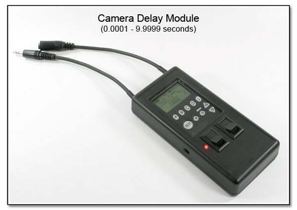 This Camera Delay Module is made to be inserted in a camera line in a Dual Head Camera Setup as a way of inserting a delay for firing the attached camera. Besides the Power ON Switch, there is a Pre-Trigger Override Switch, and the controls to set the
  actual delay time. The timed delay can be bypassed with or without actually removing the unit from the system by either powering the unit to OFF, or activatiing the Power ON Bypass Switch.
BH(***) SaberStrip Triggering w/ RadioPoppers:
(Wired IR Emitter)
CP1109 (4-9-11)
 The SaberStrip (www.SaberStrip.com) is a new "durable light modifier created for modern speed lights". Additional images and information can be found
directly on the linked web site. Shown here are 2 ways (CP1109, CP1110, just below) to reliably trigger the flash located inside the SaberStrip tube. The first way is this item CP1109 as in these images using the externally mounted RadioPopper PX Receiver that has been modified to allow an extra IR Emitter to be plugged in, and attached to the
 flash unit. The PX Receiver unit is attached to the SaberStrip tube using a specially modified PX Curved Mounting Bracket and Cinch Strap (image left). The image above shows the Primary cable having an Expansion Jack to allow additional units to be plugged in daisy-chain style. This way a single PX Reciever unit can trigger numerous flash units within other SaberStrip units. Single cables can be made as short lengths, ending in the mini plug, or the sub-mini plug, and with or without the Expansion Jack as in the image just below. Custom lengths are also
  available for connecting one unit to the next, or you can use standard mini plug splitter cables and extension cords of your own making for the interconnects. A flattened Clear Rigid Acrylic Reinforcing Tube (image below) is now being used to protect the IR Emitter and solder connection. This rigid covering is slightly thicker than the previously used epoxy reinforcement, so it should make the IR Emitter even more resistant to failure of the solder joint from any bending.
Costs: To add the specialized sync jack to the PX Receiver unit, and make the Primary IR Emitter Cable (single) is $300. It is $75 to add the Expansion Jack and Cinch Strap. The individual IR Emitter Cables ending in the mini or sub-mini plug is $60 in the PVC jacket or $75 with the more flexible rubber jacket, and each includes one Cinch Strap ($90 for the Dual IR Emitter Cable, PVC jacket, as above). The PX Curved Mounting Bracket with attached Cinch Strap is $140. The RadioPopper PX Transmitter and PX Receiver units must be sent to me in Newtown, CT (full address is on the title page of this site) for the mod and system testing, and this will naturally void the manufacturers warranty on the PX Receiver unit. You can either drill an access hole in the SaberStrip plastic base yourself, or send it along with the RadioPoppers for me to drill for no additional charge.
BJ(***) SaberStrip Triggering w/ RadioPoppers:
(Fiber Optic Setup)
CP1110 (4-9-11)
 The SaberStrip (www.SaberStrip.com) is a new "durable light modifier created for modern speed lights". Additional images and information can be found directly on the linked web site. This method of reliably triggering the flash unit located inside the SaberStrip uses the Fiber Optic Bundle, and requires no mod to the RadioPopper PX unit at all. An access hole of about 1/2 inch diameter is needed in the SaberStrip plastic base unit, as can be seen in the image just below. The hole must not be too small, otherwise rubbing and wear of the Fiber Optic Bundle will
  likely occur. You can use this image as a drilling guide, or send the base unit to me to be drilled out for no additional charge.
The PX Receiver unit is attached to the exterior of the SaberStrip mounting base using a Velcro Strip and a specially modified PX Curved Mounting Bracket, Guide Block, and Cinch Strap (image below). In this same image, you can see the single Fiber Optic Bundle with the enlarged
 end to fit the Guide Block. This enlarged end correctly centers the tip of the Fiber Optic Bundle and prevents extraneous light from affecting the IR transmission from the PX Receiver unit.
This last image (just below), shows the underside of the SaberStrip base unit and how the Fiber Optic Bundle is curved to bypass the center threaded insert, and is then passed up through the

access hole to be then held in place against the IR sensor of the flash unit using the Cinch Strap. The proper length for the Fiber optic Bundle is 9 inches for Canon flash units and is 6.5 inches for Nikon flash units.
Costs:The PX Curved Mounting Bracket, Guide Block and attached Cinch Strap is $115, and the Fiber Optic Bundle, sized to fit the Guide Block along with the Cinch Strap is $70.
BK(***) SaberStrip Triggering w/ PW FlexTT5
CP1111 (8-14-11)
 Due to the size and weight of the Pocket Wizard FlexTT5, mounting the unit to the SaberStrip (www.SaberStrip.com) needs 2 of the Cinch Straps. These 2 images (top, bottom), show the inside and outside of the mounting assembly. The offset in the mounting block allows the FlexTT5 unit to be removed by loosening the single thumbscrew, without undoing the Cinch Straps, and prevents pinching of the bottom contacts. The dense foam padding prevents rotation of the FlexTT5, and cushions
 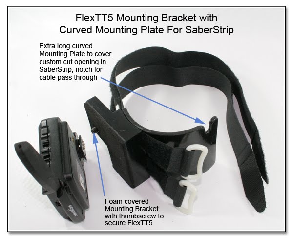 the bottom surface. The larger than needed Curved Mounting Plate shown was made to cover up, or "patch" an opening that was cut (intentionally) into the side of the SaberStrip as an access port. The notch in the Curved Mounting Plate allows the Off Camera Cord to pass into the SaberStrip without making a notch in the bottom plastic base. The flat head screws holding the Curved Mounting Plate to the FlexTT5 Mounting Block (capturing the Cinch Straps) are recessed below the curved surface so as to not scratch the finished surface of the SaberStrip.
Costs: The Curved Mounting Bracket, Cinch Straps, FlexTT5 Mounting Block and Thumbscrew assembly is $125. Connecting the FlexTT5 to the flash unit inside the SaberStrip would usually be done using an Off Camera Cord, Canon or Nikon, with either a shortened straight cable, or the existing coiled cable. This cable is then routed down and then up through the base section. If the SaberStrip is sitting on a hard surface, damage to the cord can occur unless a notch is made in the edge of the base section. It is $10 additional for me to cut and file this notch in the edge of the base section.
BL(***) RadioPopper PX Sensor Location & Testing
CP1112 (8-18-11)
 The exact location of the IR Sensor on different Canon flash units can be easily determined using the PX Mounting Bracket and Base unit. The IR Sensor for Nikon flash units is very well defined on the side fo the flash, but it almost seems that Canon has tried to hide the IR Sensor. Use the correct assembly slot of the PX Mounting Bracket in the PX Mounting Base unit, insert the flash in place, the the correct location of the IR Sensor will be located right through the small circular hole in the PX Mounting Bracket.
If you are using the RadioPopper PX Receiver in this bracket, then the alignment is automatic, as shown on the RadioPopper site. When you are trying to get the alignment correct for either the Wired IR Emitter Setup, or the Fiber Optic Setup, then the PX Mounting Bracket will give you the correct and most accurate location in a simple manner. (For a brief, but thorough comparison between the 2 methods of splitting the RadioPopper PX signal, see this section: Quad Fiber Optic vs Wired IR Emitter Setups).
 Just below is the complete procedure I use when testing the finished Wired IR Emitter setup, and to verify that the PX Receiver is getting the correct IR signal. Since the IR Signal being produced by the IR LED is not visible to the human eye, the only way to know a signal is being transmitted, and then split correctly is to see the end results of the flash being fired, and at the correct exposure.


Wired IR Emitter Test Procedure RadioPopper PX Units:
The hole in the hook Velcro (Velcro Mounting Tabs) is larger than the actual size of the IR sensor that is behind the red plastic. The hole in the soft Velcro is larger than the size of the lens of the IR Emitter...To test things and do the setup, you should use a 2 inch square of gaffers tape with the soft Velcro in the middle, and the IR Emitter opening facing away from the gaffers tape. Place this in the area of the IR sensor (IR Emitter facing to the IR Sensor of the flash) and test fire the camera...make sure the edges of the tape are secure to the flash body to seal out the extra light, After you position the IR Emitter, you might have to move it around and repeat the test firing to get a 100% firing rate. Next step is to UNPLUG the cable form the PX Receiver, and test fire the camera again. You should see the PX Receiver lights blink as it is receiving the signal from the PX Transmitter, but the flash must not fire, since it is not plugged into the PX Receiver. If it does fire, then you are getting light into the flash IR Sensor, and you should use a bigger piece of gaffers tape to block the extra light! When you find the sweet spot of the IR Sensor with the soft Velcro in place, notice this spot, and center the hole in the hook Velcro over this spot...The 1 inch square of hook Velcro will block most of the extraneous light from hitting the sensor.
Here is the same test procedure, said slightly differently:
Basically in doing the testing, you use just one flash. First take a piece of black gaffers tape, and cover the area of the sensor. Now put the ST-E2 or other Master unit in the camera hot shoe, and fire the shutter, the flash (set on Slave) should NOT fire since the IR sensor is covered by tape. If the flash does fire, then the tape is not covering the IR sensor completely, and you should either use a larger section of gaffers tape, or reposition the tape so the flash does not fire in the Slave mode (this is important). Now peel back a bit of the tape, and fire the camera again until the Slave flash fires from the signal of the ST-E2. This will give you a sense of how the Slave unit will receive the signal, and when it is blocked.
Now tape the PX Transmitter onto the ST-E2 (or other Master unit you are using), and have the PX Receiver about a foot away. Fire the camera again, the PX Transmitter will blink (sending the signal), and the PX Reciever must also blink, receiving the signal. If this is what happens, then take a single IR Emitter, peel back the tape again on the one test flash, just enough to get the IR Emitter in place, and place the IR Emitter over the sensor, CLEAR SIDE AGAINST THE SENSOR in the postion you have determined, and then cover this back up with the gaffers tape. Do not plug the cable into the PX Reciever unit at this time. Fire the camera, the PX Transmitter will blink, the PX Reciever will blink, but the flash will NOT fire since the cable is unplugged, and gaffers tape is covering the IR Emitter, and covering the sensor as when you first started. This is why you verify that covering the sensor with the tape will prevent the flash from firing; it then gives the best indication that you have the put the IR Emitter in the spot needed, since if the flash fires, it is only getting the signal from the IR Emitter, and none of the signal is coming from the ST-E2 directly. Now plug the cable into the PX Reciever, and fire the camera. If the flash doesn't fire, peel back the tape just enough to move the IR Emitter slightly, cover everything back up, and try again! If you are confused, start here, and do things step by step.
The bottom line is that no one has not been able to get this to work...said another way: EVERYONE HAS BEEN ABLE TO GET THIS TO WORK CORRECTLY. If you are having troubles, then you are not following the instructions on the testing and seup from above. Every Wired IR Setup is fully tested before it is packed for shipment back to you, which is why you are required to send one PX Transmitter along when you send the PX Receiver for the sync jack mod. After the first time, it gets much easier, and using the Velcro Mounting Tabs will make the positioning of the IR Emitters much quicker when done out in the field under pressure or time constraints.
Questions, comments, and suggestions are always welcomed!
BM(***) Fiber Optic Bundle Holding Clamp
CP1113 12-24-11
Here is a new method of holding the Fiber Optic Bundle in place without blocking the rear LCD screen: the Fiber Optic Bundle Holding Clamp. Currently, this item has only been made for the Canon 580EX unit, but it can be made for other flash units as well. This item is custom molded to grip the flash body, positions the Fiber Optic Bundle at a 90 degree angle to the IR sensor of the flash unit, and currently costs $45 each. Return to the mini posting by clicking here.
To attach the Fiber Optic Band Holding Clamp, the flash is held in one hand, and the Fiber Optic Band Holding Clamp is held in the other. The flash is inserted into the opening of the Clamp, battery door side first, and then the Clamp is rotated 90 degrees with respect to the flash so the free end of the Fiber Optic Band Holding Clamp that is currently over the front of the flash snaps over the side of the flash opposite the battery door. A small section of gaffers tape on the sides will help to prevent any sliding of the Fiber Optic Band Holding Clamp in an upwards direction.
Note: See new Extended Leg Version that will not slip just below.
Fiber Optic Bundle Holding Clamp additional images:


Just below is a modification of this Fiber Optic Bundle Holding Clamp showing the Extended Leg version which will prevent the Holding Clamp from riding upwards. It is put on and removed the same way as the smaller version without the Leg Extension, but will add $10 ($55 total) as it is more involved to hand make.


 Here is the Fiber Optic Bundle Holding Clamp - 580EX II and is a larger version, made specifically to fit the 580EX II flash unit. At the moment, these are all hand molded (not mass produced), and the 580EX II flash unit does need to be sent here for this molding (sorry). If you have a different flash, you can likely send it to me for making the Fiber Optic Bundle holding Clamp to fit that flash as well.
 Here the Fiber Optic Bundle Holding Clamp is seen installed on the Nikon SB-800. The IR Sensor is located on the right side of the flash unit, towards the front of the flash, and indicated by the small round recessed window.

BN(***) RadioPopper JrX Attached to SU-800
CP1115

CP1115:
RadioPopper JrX
Attached to SU-800
(Side View)---RadioPopper JrX Attached to SU-800 2-5-2013

Here is the newest addition to the list of Custom Combined Items, as you can see in this series of photos. (As usual, right click on any image to enlarge it in a new window.) The RadioPopper JrX Transmitter has been attached to the left side of the Nikon SU-800 Wireless Commander to allow wireless iTTL control of off camera flash unit from the SU-800, and still allow manual firing, and remote power adjustment of 3 groups of off camera flashes as controlled from the 3 knobs of the JrX Transmitter. It is $90 to add the hot shoe to the SU-800, as shown in these images. Notice that the attached hot shoe has the open end facing "forward" to best suit the attachment of the JrX transmitter unit. Attaching other small transmitters can be done in this same way, or the hot shoe can be oriented "upwards" or to the "rear" as requested. Mounting a transmitter like the CyberSync to the left side of the SU-800 would need an additional mounting block to allow for the right angle mounting of the hot shoe to then face "upwards". Write if interested.


--------------------------------------------------------------------------------
Misc Custom Connections / Projects
Note: Please remember that each of the images seen here have been made with the specific options wanted by the photog. Use these images only as a guide. Your mod will be made just as you wish, nothing more. If you have questions, please ask! If you have a special project you would like help with or trouble shooting on, send me a note! The initial consulations and discussions are free, so go ahead and ask!
--------------------------------------------------------------------------------
********************************************************************************
Purchase Info: Please Read
********************************************************************************


1 comments:
I just found this site and all I can say is WOW! Amazing and usefull projects.
Post a Comment